135
PDP-503CMX, PDP-503MXE, PDA-5002
AC IN
100 - 240V
Power Factor
Control
VSUS DC/DC
Converter
VOFS DC/DC
Converter
VADR DC/DC
Converter
6.5V DC/DC
Converter
(6.5V, 13.5V, -9V)
15V DC/DC
Converter
(15V, 12V)
ST-BY
Power Supply
STB5V
+B395V
VSUS
13.5V
12V
-9V
VOFS
-45V
VH DC/DC
Converter
VH
130V
IC5V, VF12V
DC/DC
Converter
IC5V
VF12V
VADR
61V
VRN DC/DC
Converter
VRN
-300V
225V
SW POWER SUPPLY MODULE
Y DRIVE ASSY
X DRIVE ASSY
15V DC/DC
Converter
(5V, 3.3V, 2.5V)
3.3V
2.5V
5.0V
DIGITAL VIDEO ASSY
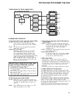
Block diagram for Power supply section
Supplementary information
1. Power on/off switch for the large-signal system (SW102)
Function:
Only the power for the small-signal system
(15V, 12V, 6.5V, 13.5V, and -9V) is on, and the
power for the large-signal system (VSUS, VADR) is
off.
Usage:
Use when only an operational check for the small-
signal system is required.
Supplementary information:
When this switch is to be used, the wires of pin 5
(DIG, ADR, and PD) of the P2 connector of the
power-supply module should be disconnected to
prevent the PD circuit from operating. To turn the
power of the large-signal system off without using this
switch, operation from an external PC through
RS-232C commands "DRF" is basically required. In
this case, the above procedure is not required, as the
PD circuit is muted by software.
3. Temperature compensation of the VOFS voltage for
the drive system
Function:
Control the power supply voltage mentioned above
according to temperature. (Temperature compensation
works so that the voltage is lowered on the lower-
temperature side, and is raised on the higher-
temperature side.)
Purpose:
To improve the yield by compensating the temperature
characteristics of the panel.
Supplementary information:
For this model, temperature compensation is perform-
ed only for the VOFS voltage, and not for the VSUS
voltage, and it is controlled by software.
4. When a fuse blows
• If a fuse blows, never turn the power on again only after
replacing the fuse. (In most cases, the fuse itself did not have
any problem. So as long as factors of overcurrent have not been
removed, chances of destruction increase every time the power
is turned on. In the worst case, about a dozen parts may be
destroyed.)
• Principally, the whole power-supply module must be replaced.
5. Voltage adjustment of the panel drive
As this model employs the electronic VR system for the VSUS
and VOFS voltages, and as the voltage-adjustment data are stored
in the DIGITAL assembly, voltage adjustment of the panel drive
is not necessary when the power-supply modules are changed.
(For VADR, VH, and VRN, adjustments with semifixed VR
controls are necessary.)
For this model, as the power-supply block has been developed
and designed by an outside vendor, at the point you know which
module is a cause of failure (through diagnosis described
elsewhere in this manual), change the corresponding modules, and
do not diagnose or repair the module.
Similarly, the switches and the semifixed VRs inside the power-
supply module must not be adjusted without a special reason.
2. 200V AC power-down switch (SW101)
Function:
While 200V AC voltage is applied, operation of the
PD circuit is turned on and off (ON when the switch is
set to 100V AC, and OFF when the switch is set to
200V AC).
Setting:
For the MXE model only, the switch is set to 200V,
and for other models, it is set to 100V.
Method of power supply ON in the large signal
system OFF state with RS-232C command
1
Confirm that this unit is the standby state.
2
Transmit RS-232C command "DRF."
3
Turn the power supply ON by remote control unit, side key
or command "PON."
∗
When turn the power supply OFF once, return to setting of
large signal system ON.
When turn the power supply ON in the large signal system
OFF, transmit "DRF" command each time.
Summary of Contents for PDA-5002
Page 5: ...5 PDP 503CMX PDP 503MXE PDA 5002 ...
Page 143: ...PDP 503CMX PDP 503MXE PDA 5002 143 Block Diagram Pin Function ...
Page 166: ...PDP 503CMX PDP 503MXE PDA 5002 166 Pin Assignment Top View CXA3516R RGB ASSY IC4603 AD PLL IC ...
Page 167: ...PDP 503CMX PDP 503MXE PDA 5002 167 Block Diagram ...
Page 168: ...PDP 503CMX PDP 503MXE PDA 5002 168 Pin Function ...
Page 169: ...PDP 503CMX PDP 503MXE PDA 5002 169 ...


