70
PDP-503CMX, PDP-503MXE, PDA-5002
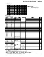
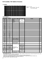
IC102
COLOR
COLOR
VOP-CT-3
0 to 255 [128]
TINT
TINT
VOP-CT-4
0 to 255 [128]
IC30
MCONTRAST
CONTRAST
VOP-CT-1
0 to 255 [128]
MBRIGHT
BRIGHT
VOP-CT-2
0 to 255 [128]
R HIGH
R. HIGH
VOP-CT-5
0 to 255 [255]
G HIGH
G. HIGH
VOP-CT-6
0 to 255 [255]
B HIGH
B. HIGH
VOP-CT-7
0 to 255 [255]
R LOW
R. LOW
VOP-CT-8
0 to 255 [128]
G LOW
G. LOW
VOP-CT-9
0 to 255 [128]
B LOW
B. LOW
VOP-CT-10
0 to 255 [128]
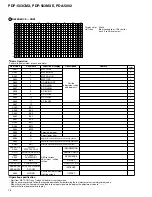
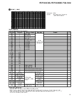
IC102
COLOR
COLOR
VOP-CM2-3
0 to 255 [128]
TINT
TINT
VOP-CM2-4
0 to 255 [128]
IC30
MCONTRAST
CONTRAST
VOP-CM2-1
0 to 255 [128]
MBRIGHT
BRIGHT
VOP-CM2-2
0 to 255 [128]
R HIGH
R. HIGH
VOP-CM2-5
0 to 255 [255]
G HIGH
G. HIGH
VOP-CM2-6
0 to 255 [255]
B HIGH
B. HIGH
VOP-CM2-7
0 to 255 [255]
R LOW
R. LOW
VOP-CM2-8
0 to 255 [128]
G LOW
G. LOW
VOP-CM2-9
0 to 255 [128]
B LOW
B. LOW
VOP-CM2-10
0 to 255 [128]
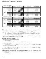
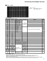
COLOR TEMP (VIDEO OPTION)
COLOR MODE2 (VIDEO OPTION)
Name
OSD Display Name
RS-232C Command
Service Factory Operation
Adjustment Range
(OFFSET Reference Value)
Name
OSD Display Name
RS-232C Command
Service Factory Operation
Adjustment Range
(OFFSET Reference Value)
Calculation of Adjustment Value in the Service Factory Mode
• As for the adjustment value in the service factory mode, it becomes an actual adjustment value that subtracted OFFSET reference value
(value in [ ] of the above table) from the value that added a REFERENCE adjustment value and an OFFSET adjustment value.
Notes: It becomes the adjustment value the value that adjusted it with REFERENCE because there is not an OFFSET adjustment value as
forR SIDE MASK LEV, G SIDE MASK LEV and B SIDE MASK LEV of item SIDE MASK LEVEL and X-SUS-B, X-SUS-G, Y-
SUS-B, Y-SUS-G, V-SUS and V-OFFSET of item DIGITAL.
• As for COLOR MODE2 and COLOR TEMP, it becomes OFFSET value of each the value that subtracted OFFSET reference value (a value
in [ ] of the above table) from a adjustment value of selected mode. It becomes a adjustment value of the last RGB 2 device (IC30 and IC102)
the value that added this OFFSET value to each adjustment item of RGB 2.
Actual Calculation Example
• Each adjustment value of SLOT/ RGB 1/RGB2/DIGITAL
(REFERENCE value)
+
{ (OFFSET value) – [OFFSET reference value] } ... Calculation of a value to add as OFFSET
• COLOR MODE2 OFFSET value
{ (COLOR MODE2 adjustment value) - [OFFSET reference value] } ... Calculation of a value to add as OFFSET for COLOR MODE2
Note: Add it only in COLOR MODE2 selection.
• COLOR TEMP OFFSET value
{(COLOR TEMP adjustment value) - [OFFSET reference value] } ... Calculation of a value to add as OFFSET for COLOR TEMP
Note: Add it only in COLOR TEMP 1,2,4 and 5 selection.
Perform the addition in the normal operation, menu mode and COLOR TEMP adjustment mode of the service factory mode (in item VIDEO
OPTION), and add OFFSET value of selected setting.
COLOR TEMP OFFSET does not add it in order to work by COLOR TEMP 3 setting in the integrator mode and in the service factory mode
except COLOR TEMP adjustment mode.
Summary of Contents for PDA-5002
Page 5: ...5 PDP 503CMX PDP 503MXE PDA 5002 ...
Page 143: ...PDP 503CMX PDP 503MXE PDA 5002 143 Block Diagram Pin Function ...
Page 166: ...PDP 503CMX PDP 503MXE PDA 5002 166 Pin Assignment Top View CXA3516R RGB ASSY IC4603 AD PLL IC ...
Page 167: ...PDP 503CMX PDP 503MXE PDA 5002 167 Block Diagram ...
Page 168: ...PDP 503CMX PDP 503MXE PDA 5002 168 Pin Function ...
Page 169: ...PDP 503CMX PDP 503MXE PDA 5002 169 ...

