8
<Ver. 2.1>
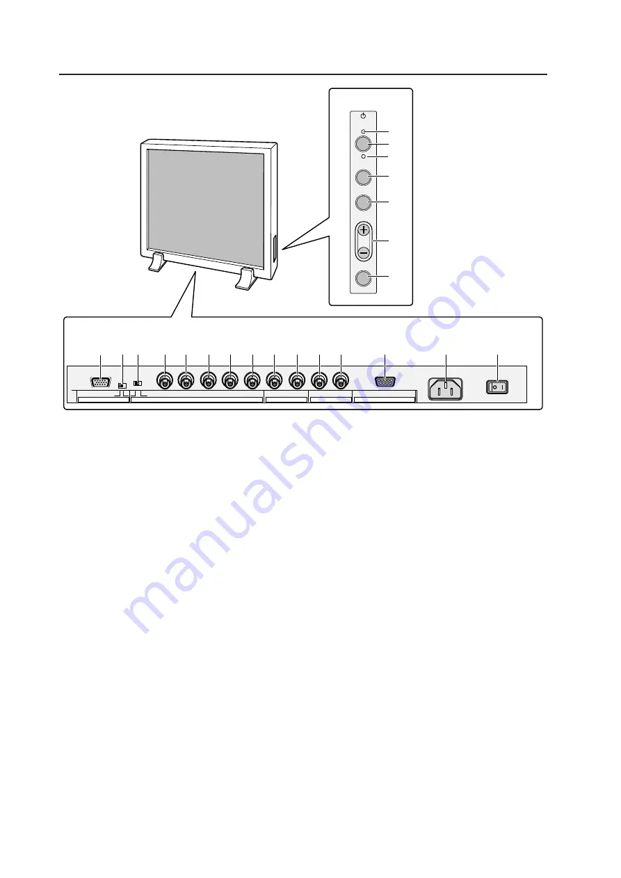
2.3 Part names
Part names
<Operation panel>
1
STANDBY/ON indicator
The switch lights in RED for STANDBY and GREEN for
ON mode.
2
Power button
Turns power on or off.
3
INPUT select button
Selects input.
4
MENU button
Used to switch the menu screen and normal screen.
5
ADJUST button
Used for picture adjustment.
6
SET button
Used to select a selected adjustment item during
picture adjustment.
<Terminals and power supply section>
RGB-2 input terminals
7
Mini D-SUB15 pin terminal
8
G-on SYNC mode select switch (ON/OFF)
If pictures take on a greenish cast when other
external equipment is connected to the RGB-2 input
terminal, turn on the G-on SYNC mode. Normally,
this switch is left off.
RGB-1 input terminals
9
Synchronizing signal input impedance select switch
(75
Ω
/2.2 k
Ω
)
0
Vertical synchronizing signal input terminal:
Switching between 75
Ω
/2.2 k
Ω
)
-
Horizontal or composite synchronizing signal input
terminal: Switching between 75
Ω
/2.2 k
Ω
=
Blue signal input terminal: 75
Ω
~
Green signal or synchronizing (ON SYNC) green
signal input terminal: 75
Ω
!
Red signal input terminal: 75
Ω
Y/C input terminal
@
Color signal input terminal: 75
Ω
#
Luminance signal input terminal: 75
Ω
VIDEO input/output terminal
$
Video output terminal: 75
Ω
(Note: Up to four units including the unit to which
the signal is first input may be connected when the
equipment is connected in series using this output
terminal. However, increasing the number of
connected units may increase noise.)
%
Video input terminal: 75
Ω
^
Control signal input terminal (RS232C)
&
AC INLET
*
Main power switch
(
KEY LOCK/UNLOCK button (hidden switch)
Use this button to disable or enable control through
the operation panel or by remote control.
STANDBY
/ON
INPUT
MENU
ADJUST
SET
VD
HD
B
G
R
C
Y
OUT
IN
75
2.2k
OFF
ON
(
Ω
)
(H/V SYNC) RGB-1 (ON SYNC)
Y/C
SYNC
G ON SYNC
VIDEO
RS-232C
RGB-2
1
2
3
4
5
6
7
8
0
9
-
=
~
!
@
#
$
%
^
*
&
˚ (
<Operation Panel>
<Terminals and power supply section>
(The terminals and power supply section are located at the back of the plasma display main body.)
Summary of Contents for PDA-4001
Page 5: ...5 Ver 2 1 Features ...
Page 19: ...19 Ver 2 1 Installation procedure ...
Page 53: ...53 Ver 2 1 Special installation Horizontal connections ...
Page 63: ...63 Ver 2 1 Mounting standard metal fixtures PDK 4001 ...
Page 69: ...69 Ver 2 1 Mounting standard metal fixtures PDK 4002 ...
Page 75: ...75 Ver 2 1 Mounting standard metal fixtures PDK 4004 ...
Page 89: ...89 Ver 2 1 Mounting standard metal fixtures PDK 4006 ...
Page 101: ...101 Ver 2 1 Mounting standard metal fixtures Precautions for installing the optional speaker ...


