5
Hardware Interface
5.1
GigE Connector
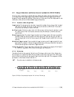
The GigE cameras are interfaced to external components via
•
an Ethernet jack (RJ45) to transmit configuration, image data and trigger.
•
a 12 pin subminiature connector for the power supply, Hirose HR10A-10P-12S (female) .
The connectors are located on the back of the camera. Fig. 5.1 shows the plugs and the status
LED which indicates camera operation.
P o w
e r S u p p l y
a n d I / O C o n n e c t o r
S t a t u s L E D
E t h e r n e t J a c k
( R J 4 5 )
Figure 5.1: Rear view of the GigE camera
5.2
Power Supply Connector
The camera requires a single voltage input (see Table 3.5). The camera meets all performance
specifications using standard switching power supplies, although well-regulated linear power
supplies provide optimum performance.
It is extremely important that you apply the appropriate voltages to your camera.
Incorrect voltages will damage the camera.
A suitable power supply can be ordered from your Photonfocus dealership.
For further details including the pinout please refer to Appendix A.
95
Summary of Contents for DR1-D1312(IE)-G2
Page 2: ......
Page 4: ...2...
Page 8: ...CONTENTS 6...
Page 14: ...2 How to get started GigE G2 Figure 2 3 PFInstaller components choice 12...
Page 96: ...4 Functionality 94...
Page 122: ...6 Software 120...
Page 128: ...8 Warranty 126...
Page 130: ...9 References 128...


