


A Pinouts
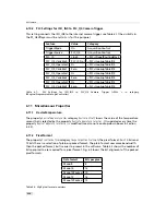
Pin
I/O Type
Name
Description
1
PWR
CAMERA_GND
Camera GND, 0V
2
PWR
CAMERA_PWR
Camera Power 12V..24V
3
O
ISO_OUT0
Default Strobe out, internally Pulled up to ISO_PWR
with 4k7 Resistor
4
I
ISO_INC0_N
INC0 differential RS-422 input, negative polarity
5
I
ISO_INC0_P
INC0 differential RS-422 input, positive polarity
6
PWR
ISO_PWR
Power supply 5V..24V for output signals; Do NOT
connect to camera Power
7
I
ISO_IN0
IN0 input signal
8
O
ISO_OUT1 (MISC)
Q1 output from PLC, no Pull up to ISO_PWR ; can be
used as additional output (by adding Pull up) or as
controllable switch (max. 100mA, no capacitive or
inductive load)
9
I
ISO_IN1(Trigger IN)
Default Trigger IN
10
I
ISO_INC1_N
INC1 differential RS-422 input, negative polarity
11
I
ISO_INC1_P
INC1 differential RS-422 input, positive polarity
12
PWR
ISO_GND
I/O GND, 0V
Table A.2: Power supply connector pin assignment
130
Summary of Contents for DR1-D1312(IE)-G2
Page 2: ......
Page 4: ...2...
Page 8: ...CONTENTS 6...
Page 14: ...2 How to get started GigE G2 Figure 2 3 PFInstaller components choice 12...
Page 96: ...4 Functionality 94...
Page 122: ...6 Software 120...
Page 128: ...8 Warranty 126...
Page 130: ...9 References 128...


