


5.5.3
Single-ended Outputs
ISO_OUT0 and ISO_OUT1 are single-ended isolated outputs.
ISO_OUT0 and ISO_OUT1 have different output circuits: ISO_OUT1 doesn’t have
a pullup resistor and can be used as additional Strobe out (by adding Pull up) or
as controllable switch. Maximal ratings that must not be exceeded: voltage: 30
V, current: 0.5 A, power: 0.5 W.
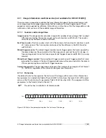
Fig. 5.6 shows the connection from the ISO_OUT0 output to a TTL logic device. PTC is a current
limiting device.
I S O _ G N D
I S O _ P W
R
P o w e r
M O S F E T
I S O _ O U T 0
P T C
4 k 7
C a m
e r a
3
1 2 p o l . H i r o s e
C o n n e c t o r
I S O _ G N D
1 2
Y O U R _ G N D
I S O _ P W
R
Y O U R _ P W
R
Y O U R _ G N D
C o n t r o l L o g i c
&
Y O U R _ P W
R
+
+
+
+
6
M a x . 3 0 V
M a x . 0 . 5 A
M a x . 0 . 5 W
Figure 5.6: Connection example to ISO_OUT0
Fig. 5.7 shows the connection from ISO_OUT1 to a TTL logic device. PTC is a current limiting
device.
I S O _ G N D
P o w e r
M O S F E T
I S O _ O U T 1
P T C
C a m
e r a
8
1 2 p o l . H i r o s e
C o n n e c t o r
I S O _ G N D
1 2
Y O U R _ G N D
Y O U R _ G N D
C o n t r o l L o g i c
&
Y O U R _ P W
R
+
4 k 7
+
Y O U R _ P W
R
M a x . 3 0 V
M a x . 0 . 5 A
M a x . 0 . 5 W
Figure 5.7: Connection from the ISO_OUT1 output to a TTL logic device
.
5.5 Trigger and Strobe Signals for GigE G2 Cameras
101
Summary of Contents for DR1-D1312(IE)-G2
Page 2: ......
Page 4: ...2...
Page 8: ...CONTENTS 6...
Page 14: ...2 How to get started GigE G2 Figure 2 3 PFInstaller components choice 12...
Page 96: ...4 Functionality 94...
Page 122: ...6 Software 120...
Page 128: ...8 Warranty 126...
Page 130: ...9 References 128...


