


5 Hardware Interface
5.6
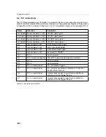
PLC connections
The PLC (Programmable Logic Controller) is a powerful device where some camera inputs and
outputs can be manipulated and software interrupts can be generated. Sample settings and an
introduction to PLC are shown in Section 6.10. PLC is described in detail in the document [PLC].
Name
Direction
Description
A0 (Line0)
Power connector -> PLC
ISO_IN0 input signal
A1(Line1)
Power connector -> PLC
ISO_IN1 input signal
A2 (Line2)
Power connector -> PLC
ISO_INC0 input signal
A3 (Line3)
Power connector -> PLC
ISO_INC1 input signal
A4
camera head -> PLC
FVAL (Frame Valid) signal
A5
camera head -> PLC
LVAL (Line Valid) signal
A6
camera head -> PLC
DVAL (Data Valid) signal
A7
camera head -> PLC
Reserved (CL_SPARE)
Q0
PLC ->
not connected
Q1
PLC -> power connector
ISO_OUT1 output signal (signal is inverted)
Q2
PLC ->
not connected
Q3
PLC ->
not connected
Q4
PLC -> camera head
PLC_Q4 camera trigger
Q5
PLC -> camera head
PLC_Q5 (only available on cameras with Counter
Reset External feature.
Q6
PLC -> camera head
Incremental encoder A signal (only available on
cameras with AB Trigger feature
Q7
PLC -> camera head
Incremental encoder B signal (only available on
cameras with AB Trigger feature.
Table 5.2: Connections to/from PLC
104
Summary of Contents for DR1-D1312(IE)-G2
Page 2: ......
Page 4: ...2...
Page 8: ...CONTENTS 6...
Page 14: ...2 How to get started GigE G2 Figure 2 3 PFInstaller components choice 12...
Page 96: ...4 Functionality 94...
Page 122: ...6 Software 120...
Page 128: ...8 Warranty 126...
Page 130: ...9 References 128...


