


5 Hardware Interface
5.5
Trigger and Strobe Signals for GigE G2 Cameras
5.5.1
Overview
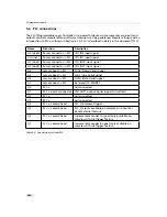
The 12-pol. Hirose power connector contains two external trigger inputs, two strobe outputs
and two differential RS-422 inputs. All inputs and outputs are connected to the Programmable
Logic Controller (PLC) (see also Section 5.6) that offers powerful operations.
The pinout of the power connector is described in Section A.1.
ISO_INC0 and ISO_INC1 RS-422 inputs have -10 V to +13 V extended common
mode range.
ISO_OUT0 and ISO_OUT1 have different output circuits (see also Section 5.5.2).
A suitable trigger breakout cable for the Hirose 12 pol. connector can be ordered
from your Photonfocus dealership.
Simulation with LTSpice is possible, a simulation model can be downloaded from
our web site www.photonfocus.com on the software download page (in Support
section). It is filed under "Third Party Tools".
Fig. 5.3 shows the schematic of the inputs and outputs. All inputs and outputs are isolated.
ISO_VCC is an isolated, internally generated voltage.
.
98
Summary of Contents for DR1-D1312(IE)-G2
Page 2: ......
Page 4: ...2...
Page 8: ...CONTENTS 6...
Page 14: ...2 How to get started GigE G2 Figure 2 3 PFInstaller components choice 12...
Page 96: ...4 Functionality 94...
Page 122: ...6 Software 120...
Page 128: ...8 Warranty 126...
Page 130: ...9 References 128...


