


4 Functionality
camera environment to allow robust integration of the camera into the vision system. In the
signal isolator the trigger signal is delayed by time t
d
−
iso
−
input
. This signal is clocked into the
FPGA which leads to a jitter of t
jitter
. The pulse can be delayed by the time t
trigger
−
delay
which
can be configured by a user defined value via camera software. The trigger offset delay
t
trigger
−
offset
results then from the synchronous design of the FPGA state machines. The
exposure time t
exposure
is controlled with an internal exposure time controller.
The trigger pulse from the internal camera control starts also the strobe control state machines.
The strobe can be delayed by t
strobe
−
delay
with an internal counter which can be controlled by
the customer via software settings. The strobe offset delay t
strobe
−
delay
results then from the
synchronous design of the FPGA state machines. A second counter determines the strobe
duration t
strobe
−
duration
(strobe-duration). For a robust system design the strobe output is also
isolated from the camera electronic which leads to an additional delay of t
d
−
iso
−
output
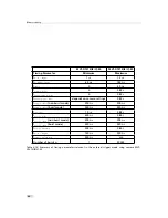
. Section
4.4.6 gives an overview over the minimum and maximum values of the parameters.
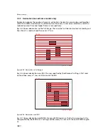
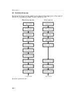
External Trigger with Pulsewidth controlled Exposure Time
In the external trigger mode with Pulsewidth controlled exposure time the rising edge of the
trigger pulse starts the camera states machine, which controls the sensor. The falling edge of
the trigger pulse stops the image acquisition. Additionally the optional external strobe output
is controlled by the rising edge of the trigger pulse. Timing diagram Fig. 4.34 shows the
detailed timing for the external trigger mode with pulse width controlled exposure time.
e x t e r n a l t r i g g e r p u l s e i n p u t
t r i g g e r a f t e r i s o l a t o r
t r i g g e r p u l s e r i s i n g e d g e c a m
e r a c o n t r o l
d e l a y e d t r i g g e r r i s i n g e d g e f o r s h u t t e r s e t
i n t e r n a l s h u t t e r c o n t r o l
d e l a y e d t r i g g e r f o r s t r o b e c o n t r o l
i n t e r n a l s t r o b e c o n t r o l
e x t e r n a l s t r o b e p u l s e o u t p u t
t
d - i s o - i n p u t
t
j i t t e r
t
t r i g g e r - d e l a y
t
e x p o s u r e
t
s t r o b e - d e l a y
t
d - i s o - o u t p u t
t
s t r o b e - d u r a t i o n
t r i g g e r p u l s e f a l l i n g e d g e c a m
e r a c o n t r o l
d e l a y e d t r i g g e r f a l l i n g e d g e s h u t t e r r e s e t
t
j i t t e r
t
t r i g g e r - d e l a y
t
e x p o s u r e
t
t r i g g e r - o f f s e t
t
s t r o b e - o f f s e t
Figure 4.34: Timing diagram for the Pulsewidth controlled exposure time
62
Summary of Contents for DR1-D1312(IE)-G2
Page 2: ......
Page 4: ...2...
Page 8: ...CONTENTS 6...
Page 14: ...2 How to get started GigE G2 Figure 2 3 PFInstaller components choice 12...
Page 96: ...4 Functionality 94...
Page 122: ...6 Software 120...
Page 128: ...8 Warranty 126...
Page 130: ...9 References 128...


