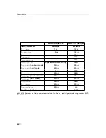


4 Functionality
When the Region-LUT feature is enabled, then the LUTs are only active in a user defined
region. Examples are shown in Fig. 4.48 and Fig. 4.49.
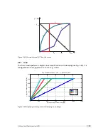
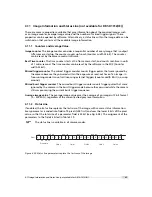
Fig. 4.48 shows an example of overlapping Region-LUTs. LUT 0, LUT 1 and Region LUT are
enabled. LUT 0 is active in region 0 ((x00, x01), (y00, y01)) and it supersedes LUT 1 in the
overlapping region. LUT 1 is active in region 1 ((x10, x11), (y10, y11)).
L U T 0
( 0 , 0 )
( 1 3 1 1 , 1 0 8 1 )
L U T 1
x 0 0
x 1 0
x 0 1
x 1 1
y 1 0
y 0 0
y 0 1
y 1 1
Figure 4.48: Overlapping Region-LUT example
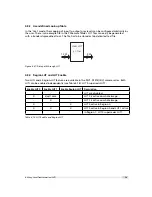
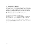
Fig. 4.49 shows an example of keyhole inspection in a laser welding application. LUT 0 and LUT
1 are used to enhance the contrast by applying optimized transfer curves to the individual
regions. LUT 0 is used for keyhole inspection. LUT 1 is optimized for seam finding.
L U T 0
( 0 , 0 )
( 1 3 1 1 , 1 0 8 1 )
L U T 1
( 0 , 0 )
( 1 3 1 1 , 1 0 8 1 )
L U T 1
L U T 0
Figure 4.49: Region-LUT in keyhole inspection
.
80
Summary of Contents for DR1-D1312(IE)-G2
Page 2: ......
Page 4: ...2...
Page 8: ...CONTENTS 6...
Page 14: ...2 How to get started GigE G2 Figure 2 3 PFInstaller components choice 12...
Page 96: ...4 Functionality 94...
Page 122: ...6 Software 120...
Page 128: ...8 Warranty 126...
Page 130: ...9 References 128...


