


5.5.4
Differential RS-422 Inputs
ISO_INC0 and ISO_INC1 are isolated differential RS-422 inputs (see also Fig. 5.3). They are
connected to a Maxim MAX3098 RS-422 receiver device. Please consult the data sheet of the
MAX3098 for connection details.
Don’t connect single-ended signals to the differential inputs ISO_INC0 and
ISO_INC1 (see also Fig. 5.10).
R X R S 4 2 2
I S O _ I N C x _ P
I S O _ I N C x _ N
1 2 p o l . H i r o s e
C o n n e c t o r
Y O U R _ G N D
5 V T T L L o g i c L e v e l
C a m
e r a
Figure 5.10: Incorrect connection to ISO_INC inputs
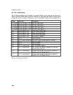
5.5.5
Master / Slave Camera Connection
The trigger input of one Photonfocus G2 camera can easily connected to the strobe output of
another Photonfocus G2 camera as shown in Fig. 5.11. This results in a master/slave mode
where the slave camera operates synchronously to the master camera.
I S O _ G N D
I S O _ P W
R
P o w e r
M O S F E T
I S O _ O U T 0
P T C
4 k 7
I S O _ G N D
I S O _ G N D
I S O _ V C C
e n h a n c e d
P o w e r F E T
4 . 7 V
1 0 k
I S O _ I N 0
M a s t e r C a m
e r a
S l a v e C a m
e r a
3
7
H i r o s e
C o n n e c t o r s
+
+
I S O _ G N D
I S O _ G N D
1 2
1 2
6
I S O _ P W
R
Figure 5.11: Master / slave connection of two Photonfocus G2 cameras
.
5.5 Trigger and Strobe Signals for GigE G2 Cameras
103
Summary of Contents for DR1-D1312(IE)-G2
Page 2: ......
Page 4: ...2...
Page 8: ...CONTENTS 6...
Page 14: ...2 How to get started GigE G2 Figure 2 3 PFInstaller components choice 12...
Page 96: ...4 Functionality 94...
Page 122: ...6 Software 120...
Page 128: ...8 Warranty 126...
Page 130: ...9 References 128...


