


Mounting, removal, electrical installation, and replacement
108580_en_02
PHOENIX CONTACT
10. Remove the parameterization memory from the device that was replaced and insert it
in the replacement device. See Section
Section “Inserting/removing the SD card
(parameterization memory)” on page 73
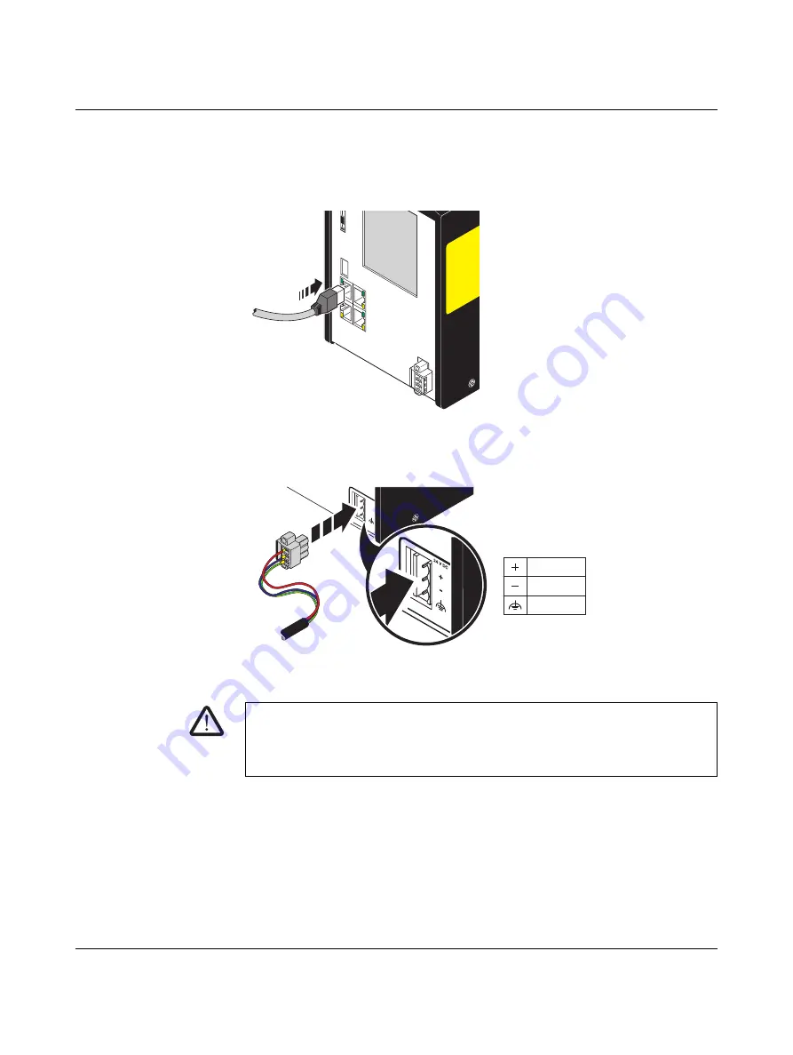
11. Connect the Ethernet cable, if present.
Figure 3-13
Establishing the Ethernet connection
12. Connect the power supply with the RFC.
Figure 3-14
Connecting the power supply
13. When restarting the RFC 4072S after replacement, first carry out the appropriate mea-
sures specified in the validation plan for the machine/system. Follow the instructions
and corresponding notes in
Section “Restart after replacing the RFC 4072S” on
.
WARNING: Do not connect the RFC 4072S supply voltage yet.
Take appropriate measures to ensure that your machine/system does not present any
danger for the time specified in the validation plan for the machine/system and for the val-
idation measures to be carried out when replacing the RFC 4072S.
24
V D
C
+
-
24 V DC
0 V
FE
107586A006
Summary of Contents for RFC 4072S
Page 22: ...RFC 4072S 22 272 PHOENIX CONTACT 108580_en_02...
Page 68: ...RFC 4072S 68 272 PHOENIX CONTACT 108580_en_02...
Page 82: ...RFC 4072S 82 272 PHOENIX CONTACT 108580_en_02...
Page 142: ...RFC 4072S 142 272 PHOENIX CONTACT 108580_en_02...
Page 154: ...RFC 4072S 154 272 PHOENIX CONTACT 108580_en_02...
Page 222: ...RFC 4072S 222 272 PHOENIX CONTACT 108580_en_02...
Page 234: ...RFC 4072S 234 272 PHOENIX CONTACT 108580_en_02...
Page 254: ...RFC 4072S 254 272 PHOENIX CONTACT 108580_en_02...
Page 264: ...RFC 4072S 264 272 PHOENIX CONTACT 108580_en_02...
Page 268: ...RFC 4072S 268 272 PHOENIX CONTACT 108580_en_02...
Page 271: ......