


PCAN-Router Pro – User Manual
65
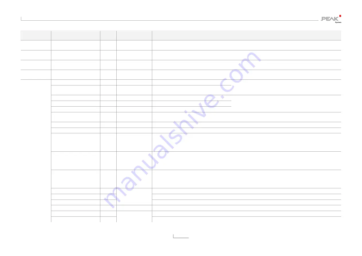
I/O Function
I/O Number
Number
of Bits
Value Range
Function
None
No function
Can be used as place-holder if the corresponding input or output has no function.
Const
(CCh)
(Diverse values)
Diverse constants
Read only; can be used as input constants
Positive Const
(CDh)
0 to 255
Positive constants
Read only; can be used as input constants
Negative Const
(CEh)
0 to -255
Negative constants
Read only; can be used as input constants
Conf Ver Main
8
0 - 255
Main version number of the configuration
Conf Ver Sub
8
0 - 255
Secondary version number of the
configuration
Can be specified in the PPCAN-Editor 2 during the module-
specific settings
FW Ver Main
3
0 - 7
Main version number of the firmware
FW Ver Sub
5
0 - 31
Secondary version number of the firmware
FW Build
8
0 - 255
Build version number of the firmware
For information purposes
Module ID
4
0 - 15
Router ID
Position of the corresponding rotary switch on the board of the PCAN-Router Pro (see section 3.3 on page 18)
Tx Msg Count CAN x
32
Number of transmitted CAN messages on CAN channel x
Rx Msg Count CAN x
32
Number of received CAN messages on CAN channel x
RTC Time
32
Value from bit
pattern (see right)
Read current time from the real-time clock
Bit pattern:
hhhhhhhh mmmmmmmm ssssssss cccccccc
h
= hours,
m
= minutes,
s
= seconds,
c
= hundreds
RTC Date
32
Value from bit
pattern (see right)
Read current date from the real-time clock
Bit pattern:
WWWW---- DDDDDDDD MMMMMMMM YYYYYYYY
W
= day of week,
D
= day of month,
M
= month,
Y
= year
RTC Alarm
32
Value from bit
pattern (see right)
Read set alarm time from the real-time clock
Bit pattern:
--MMMMMM MMDDDDDh hhhhmmmm mmssssss
M
= month,
D
= day of month,
h
= hour,
m
= minute,
s
= second
Main Cycle Counter
32
Gives the average duration for a computation cycle of the firmware (since the last polling)
Main Cycle Time Max [ms]
16
Gives the maximum duration for a computation cycle of the firmware
Main Cycle Time Avg [
μ
s] 16
0 - 65535
Mean duration based on 1000 calculation cycles
Rx Traffic Indicator CAN x
1
0, 1
Indicates the reception of CAN messages (monoflop 100 ms)
Rx Error Counter CAN x
8
Counter of the CAN controller for reception errors
Special In
(F0h)
Tx Error Counter CAN x
8
0 - 255
Counter of the CAN controller for transmission errors