background image

HY13-1527-M1/US

Torqmotor™ Service Procedure

TF, TG, TH and TL Series

Parker Hannifin Corporation

Hydraulic Pump/Motor Division

Greeneville, TN 37745  US

43

Offer of Sale

The items described in this document and other documents and descriptions provided by Parker Hannifin Corporation, its subsidiaries and its authorized distributors (“Seller”) are 
hereby offered for sale at prices to be established by Seller. This offer and its acceptance by any customer (“Buyer”) shall be governed by all of the following Terms and Conditions. 
Buyer’s order for any item described in its document, when communicated to Seller verbally, or in writing, shall constitute acceptance of this offer. All goods, services or work 
described will be referred to as “Products”.

1. Terms and Conditions.

 Seller’s willingness to offer Products, or accept an order 

for Products, to or from Buyer is subject to these Terms and Conditions or any newer 
version of the terms and conditions found on-line at www.parker.com/saleterms/. Seller 
objects to any contrary or additional terms or conditions of Buyer’s order or any other 
document issued by Buyer.

2. Price Adjustments; Payments.

 Prices stated on Seller’s quote or other documenta-

tion offered by Seller are valid for 30 days, and do not include any sales, use, or other 
taxes unless specifically stated. Unless otherwise specified by Seller, all prices are 
F.C.A. Seller’s facility (INCOTERMS 2010).  Payment is subject to credit approval and is 
due 30 days from the date of invoice or such other term as required by Seller’s Credit 
Department, after which Buyer shall pay interest on any unpaid invoices at the rate of 
1.5% per month or the maximum allowable rate under applicable law.

3. Delivery Dates; Title and Risk; Shipment.

 All delivery dates are approximate and 

Seller shall not be responsible for any damages resulting from any delay. Regardless 
of the manner of shipment, title to any products and risk of loss or damage shall pass 
to Buyer upon placement of the products with the shipment carrier at Seller’s facility. 
Unless otherwise stated, Seller may exercise its judgment in choosing the carrier and 
means of delivery. No deferment of shipment at Buyers’ request beyond the respec-
tive dates indicated will be made except on terms that will indemnify, defend and hold 
Seller harmless against all loss and additional expense.  Buyer shall be responsible for 
any additional shipping charges incurred by Seller due to Buyer’s acts or omissions.

4. Warranty.

 Seller warrants that the Products sold hereunder shall be free from de-

fects in material or workmanship for a period of eighteen months from the date of 
delivery to Buyer or 2,000 hours of normal use, whichever occurs first. The prices 
charged for Seller’s products are based upon the exclusive limited warranty stated 
above, and upon the following disclaimer: 

DISCLAIMER OF WARRANTY:

 THIS WAR-

RANTY COMPRISES THE SOLE AND ENTIRE WARRANTY PERTAINING TO PROD-
UCTS PROVIDED HEREUNDER. SELLER DISCLAIMS ALL OTHER WARRANTIES, 
EXPRESS AND IMPLIED, INCLUDING DESIGN, MERCHANTABILITY AND FITNESS 
FOR A PARTICULAR PURPOSE.

5. Claims; Commencement of Actions.

 Buyer shall promptly inspect all Products 

upon delivery. No claims for shortages will be allowed unless reported to the Seller 
within 10 days of delivery. No other claims against Seller will be allowed unless as-
serted in writing within 30 days after delivery.  Buyer shall notify Seller of any alleged 
breach of warranty within 30 days after the date the defect is or should have been 
discovered by Buyer. Any action based upon breach of this agreement or upon any 
other claim arising out of this sale (other than an action by Seller for an amount due on 
any invoice) must be commenced within 12 months from the date of the breach without 
regard to the date breach is discovered.

6. LIMITATION OF LIABILITY.

 UPON NOTIFICATION, SELLER WILL, AT ITS OP-

TION, REPAIR OR REPLACE A DEFECTIVE PRODUCT, OR REFUND THE PURCHASE 
PRICE. IN NO EVENT SHALL SELLER BE LIABLE TO BUYER FOR ANY SPECIAL, 
INDIRECT, INCIDENTAL OR CONSEQUENTIAL DAMAGES ARISING OUT OF, OR AS 
THE RESULT OF, THE SALE, DELIVERY, NON-DELIVERY, SERVICING, USE OR LOSS 
OF USE OF THE PRODUCTS OR ANY PART THEREOF, OR FOR ANY CHARGES OR 
EXPENSES OF ANY NATURE INCURRED WITHOUT SELLER’S WRITTEN CONSENT, 
EVEN IF SELLER HAS BEEN NEGLIGENT, WHETHER IN CONTRACT, TORT OR OTH-
ER LEGAL THEORY. IN NO EVENT SHALL SELLER’S LIABILITY UNDER ANY CLAIM 
MADE BY BUYER EXCEED THE PURCHASE PRICE OF THE PRODUCTS.

7. User Responsibility.

 The user, through its own analysis and testing, is solely re-

sponsible for making the final selection of the system and Product and assuring that 
all performance, endurance, maintenance, safety and warning requirements of the 
application are met. The user must analyze all aspects of the application and follow 
applicable industry standards and Product information. If Seller provides Product or 
system options, the user is responsible for determining that such data and specifica-
tions are suitable and sufficient for all applications and reasonably foreseeable uses of 
the Products or systems.

8. Loss to Buyer’s Property.

 Any designs, tools, patterns, materials, drawings, confi-

dential information or equipment furnished by Buyer or any other items which become 
Buyer’s property, will be considered obsolete and may be destroyed by Seller after two 
consecutive years have elapsed without Buyer ordering the items manufactured using 
such property. Seller shall not be responsible for any loss or damage to such property 
while it is in Seller’s possession or control.

9. Special Tooling.

 A tooling charge may be imposed for any special tooling, including 

without limitation, dies, fixtures, molds and patterns, acquired to manufacture Prod-
ucts. Such special tooling shall be and remain Seller’s property notwithstanding pay-
ment of any charges by Buyer. In no event will Buyer acquire any interest in apparatus 
belonging to Seller which is utilized in the manufacture of the Products, even if such 
apparatus has been specially converted or adapted for such manufacture and notwith-
standing any charges paid by Buyer. Unless otherwise agreed, Seller shall have the 
right to alter, discard or otherwise dispose of any special tooling or other property in its 
sole discretion at any time.

10. Buyer’s Obligation; Rights of Seller.

 To secure payment of all sums due or oth-

erwise, Seller shall retain a security interest in the goods delivered and this agreement 
shall be deemed a Security Agreement under the Uniform Commercial Code. Buyer 
authorizes Seller as its attorney to execute and file on Buyer’s behalf all documents 
Seller deems necessary to perfect its security interest. 

11. Improper use and Indemnity.

 Buyer shall indemnify, defend, and hold Seller harm-

less from any claim, liability, damages, lawsuits, and costs (including attorney fees), 
whether for personal injury, property damage, patent, trademark or copyright infringe-

ment or any other claim, brought by or incurred by Buyer, Buyer’s employees, or any 
other person, arising out of: (a) improper selection, improper application or other mis-
use of Products purchased by Buyer from Seller; (b) any act or omission, negligent 
or otherwise, of Buyer; (c) Seller’s use of patterns, plans, drawings, or specifications 
furnished by Buyer to manufacture Product; or (d) Buyer’s failure to comply with these 
terms and conditions. Seller shall not indemnify Buyer under any circumstance except 
as otherwise provided.

12. Cancellations and Changes.

 Orders shall not be subject to cancellation or change 

by Buyer for any reason, except with Seller’s written consent and upon terms that will 
indemnify, defend and hold Seller harmless against all direct, incidental and conse-
quential loss or damage. Seller may change product features, specifications, designs 
and availability with notice to Buyer.

13. Limitation on Assignment.

 Buyer may not assign its rights or obligations under 

this agreement without the prior written consent of Seller.

14. Force Majeure. 

Seller does not assume the risk and shall not be liable for delay 

or failure to perform any of Seller’s obligations by reason of circumstances beyond the 
reasonable control of Seller (hereinafter “Events of Force Majeure”).  Events of Force 
Majeure shall include without limitation: accidents, strikes or labor disputes, acts of 
any government or government agency, acts of nature, delays or failures in delivery 
from carriers or suppliers, shortages of materials, or any other cause beyond Seller’s 
reasonable control.  

15. Waiver and Severability.

 Failure to enforce any provision of this agreement will 

not waive that provision nor will any such failure prejudice Seller’s right to enforce that 
provision in the future.  Invalidation of any provision of this agreement by legislation or 
other rule of law shall not invalidate any other provision herein. The remaining provi-
sions of this agreement will remain in full force and effect.

16. Termination.

 Seller may terminate this agreement for any reason and at any time 

by giving Buyer thirty (30) days written notice of termination.  Seller may immediately 
terminate this agreement, in writing, if Buyer:  (a) commits a breach of any provision of 
this agreement (b) appointments a trustee, receiver or custodian for all or any part of 
Buyer’s property (c) files a petition for relief in bankruptcy on its own behalf, or by a third 
party (d) makes an assignment for the benefit of creditors, or (e) dissolves or liquidates 
all or a majority of its assets.

17. Governing Law.

 This agreement and the sale and delivery of all Products here-

under shall be deemed to have taken place in and shall be governed and construed 
in accordance with the laws of the State of Ohio, as applicable to contracts executed 
and wholly performed therein and without regard to conflicts of laws principles. Buyer 
irrevocably agrees and consents to the exclusive jurisdiction and venue of the courts 
of Cuyahoga County, Ohio with respect to any dispute, controversy or claim arising out 
of or relating to this agreement. 

18. Indemnity for Infringement of Intellectual Property Rights.

 Seller shall have 

no liability for infringement of any patents, trademarks, copyrights, trade dress, trade 
secrets or similar rights except as provided in this Section. Seller will defend and in-
demnify Buyer against allegations of infringement of U.S. patents, U.S. trademarks, 
copyrights, trade dress and trade secrets (“Intellectual Property Rights”). Seller will 
defend at its expense and will pay the cost of any settlement or damages awarded in 
an action brought against Buyer based on an allegation that a Product sold pursuant 
to this Agreement infringes the Intellectual Property Rights of a third party. Seller’s 
obligation to defend and indemnify Buyer is contingent on Buyer notifying Seller within 
ten (10) days after Buyer becomes aware of such allegations of infringement, and Seller 
having sole control over the defense of any allegations or actions including all negotia-
tions for settlement or compromise. If a Product is subject to a claim that it infringes the 
Intellectual Property Rights of a third party, Seller may, at its sole expense and option, 
procure for Buyer the right to continue using the Product, replace or modify the Prod-
uct so as to make it noninfringing, or offer to accept return of the Product and return 
the purchase price less a reasonable allowance for depreciation. Notwithstanding the 
foregoing, Seller shall have no liability for claims of infringement based on information 
provided by Buyer, or directed to Products delivered hereunder for which the designs 
are specified in whole or part by Buyer, or infringements resulting from the modification, 
combination or use in a system of any Product sold hereunder. The foregoing provi-
sions of this Section shall constitute Seller’s sole and exclusive liability and Buyer’s sole 
and exclusive remedy for infringement of Intellectual Property Rights.

19. Entire Agreement.

 This agreement contains the entire agreement between the 

Buyer and Seller and constitutes the final, complete and exclusive expression of the 
terms of sale.  All prior or contemporaneous written or oral agreements or negotiations 
with respect to the subject matter are herein merged.

20. Compliance with Law, U.K. Bribery Act and U.S. Foreign Corrupt Practices 
Act. 

Buyer agrees to comply with all applicable laws and regulations, including both 

those of the United Kingdom and the United States of America, and of the country or 
countries of the Territory in which Buyer may operate, including without limitation the U. 
K. Bribery Act, the U.S. Foreign Corrupt Practices Act (“FCPA”) and the U.S. Anti-Kick-
back Act (the “Anti-Kickback Act”), and agrees to indemnify and hold harmless Seller 
from the consequences of any violation of such provisions by Buyer, its employees or 
agents.  Buyer acknowledges that they are familiar with the provisions of the U. K. Brib-
ery Act, the FCPA and the Anti-Kickback Act, and certifies that Buyer will adhere to the 
requirements thereof.  In particular, Buyer represents and agrees that Buyer shall not 
make any payment or give anything of value, directly or indirectly to any governmental 
official, any foreign political party or official thereof, any candidate for foreign political 
office, or any commercial entity or person, for the purpose of influencing such person 
to purchase products or otherwise benefit the business of Seller.

2/12

Summary of Contents for Torqmotor TF Series

Page 1: ...HY13 1527 M1 US Torqmotor Service Procedure Effective April 2015 TF TG TH and TL Series Low Speed High Torque Hydraulic Torqmotors ...

Page 2: ... product catalog Due to the variety of operating conditions and applications for these products or systems the user through its own analysis and testing is solely responsible for making the final selection of the products and systems and assuring that all performance safety and warning requirements of the application are met The products described herein including without limitation product featur...

Page 3: ... and complete information and instructions regard ing the techniques and tools required for maintaining repairing and servicing the complete line of Parker TF TG TH and TL TorqmotorTM Units However despite the care and effort taken in preparing this general Service Manual Parker makes no warranties that a the Service Manual or any explanations illustrations information techniques or tools describe...

Page 4: ...ty because of superior lubrication and minimum drive spline wear Zero leak commutation valve provides greater more consistent volumetric ef ficiency Torqmotor TF Series features include Heavy duty thrust and roller bearings for up to twice side load capacity to the previ ous motor Roller vanes to reduce friction and inter nal leakage and to maintain efficiency A patented orbiting commutation syste...

Page 5: ...the procedure you should follow Column 3 illustrates this procedure with pho tographs Read all material carefully and pay special attention to the notes cautions and warnings A page with the Torqmotor exploded assembly view is provided several places in this manual The compo nent part names and item numbers assigned on this exploded assembly view correspond with names and item numbers in parenthes...

Page 6: ...ts or slipping belts Hydraulic Components If you think the problem is caused by a hydraulic com ponent start by checking the easy to reach items Check all hoses and lines for cracks hardening or other signs of wear Reroute any usable hoses that are kinked severely bent or that rest against hot engine parts Look for leaks especially at couplings and fittings Replace any hoses or lines that don t me...

Page 7: ...eakage 3 Severely worn or damaged internal splines 4 Excessive heat a Check for faulty relief valve and adjust or replace as required b Check for and repair worn pump c Check for and use correct oil for temperature of operation Replace worn rotor set by disassembling Torqmotor unit Replace rotor set drive link and coupling shaft by disassembling Torqmotor unit Locate excessive heat source usually ...

Page 8: ...sult factory Special bearing mandrel for TF TG TJ Torqmotors SEE FIGURE 1 Feeler gage 005 inch 13 mm TH Torqmotors require blind hole bearing puller for a 1 575 inch dia 40 0 mm and 2 130 inch dia 54 1 mm bearings TF TG TL Torqmotors require blind hole bearing puller for 1 400 inch dia 35 6 mm and 2 130 inch dia 54 1 mm bearings Clean corrosion resistant grease Part 406018 is included in each seal...

Page 9: ...460 11 68 2 122 53 90 470 11 94 2 233 56 72 500 12 70 2 235 56 77 585 14 86 2 483 63 07 595 15 11 2 485 63 12 660 16 76 2 500 63 5 675 17 15 2 88 73 2 1 058 26 87 Torque Chart Part Name Item Number Torque bolt 3 8 24 UNF 2A 1 1A 1B or 1C 45 55 ft lbs 60 76 N m bolt 5 8 18 UNF 2A 12D 140 180 ft lbs 190 244 N m nut 1 20 UNEF 2B 12B TF TG TL 300 400 ft lbs 407 542 N m nut 1 1 8 18 UNEF 2B 12B TG TH 3...

Page 10: ...4 Seal Ring 5 5 Commutator 6 Commutator Ring 7 Manifold 8 Rotor Set 8a Rotor 8b Stator or Stator Half 8c Vane 7 8d Stator Half 8e Vane 7 9 Wear Plate 10 Drive Link 11 Thrust Bearing 12 Coupling Shaft 12a Key 12b Nut 12c Washer 12d Bolt 12e Lockwasher 12f Retaining Ring 13 Bearing Inner 14 Thrust Washer 15 Thrust Bearing 16 Seal 17 Backup Ring Items not sold separately Sold as matched sets only 18 ...

Page 11: ... 028511 47 Seal Dirt and Water 478030 48 Snap Ring 401623 49 Drive Shaft 14 Tooth Spline 093043 49 Straight Key Shaft 1 1 4 093044 50 Thrust Washer 400141 Yellow 028027 132 134 White 028028 138 140 Green 028029 144 146 Blue 028030 150 152 Red 028031 156 158 Black 028032 162 164 51 Bearing and Cone Assembly 2 067033 52 Bearing Cup 2 400140 53 Retaining Ring 401623 55 Plug 036024 56 Housing ME012013...

Page 12: ...477342 068024 071019 400136 069017 028515 068027 478035 029118 SERIES EXPLODED VIEW SPEED SENSOR ITEM 2 1 18 18 18 DESCRIPTION END SERVICE SERVICE MOUNTING 8 PORTING COVER HOUSING ASS Y HOUSING ASS Y SENSOR MS Standard 4 Bolt 7 8 O Ring ME016000 ME012001A1 ME012301A1 455063 US Wheel Mt 4 Bolt 7 8 O Ring ME016000 ME012002A1 ME012302A1 455063 AS SAE A 2 Bolt 7 8 O Ring ME016000 ME012006A1 ME012306A1...

Page 13: ...n Item 1 ME016000 032435 032819 032817 455063 OPTION GROUP For reverse timed manifold use ME015001 1 Service housing ass y ITEM 18 with part number suffix A1 includes ITEM 13 14 two req d 15 and 19 2 Select the required bolt number in designated DISPLACEMENT GROUP under bolt ITEM 1 1A 1B or 1C shown in designated OPTION GROUP 3 1 20 UNEF slotted nut 025113 is required on 1 1 4 tapered shaft if the...

Page 14: ...1395 021388 021388 021416 3 5036 ME487003 N A ME483000 7 3285 0960 58 5 021396 021389 021389 021399 4 2536 ME587003 N A ME583000 8 0815 DISPLACEMENT GROUP EXPLODED VIEW SPEED SENSOR ITEM 1 18 1 18A 18 18 DESCRIPTION SERVICE SERVICE MOUNTING 8 PORTING HOUSING ASS Y O RING 2 HOUSING ASS Y SENSOR MS Standard 4 Bolt 7 8 O Ring ME012001A3 ME012301A3 455063 US Wheel Mt 4 Bolt 7 8 O Ring ME012002A3 ME012...

Page 15: ...al 032817 inner seal 028515 and 029118 back washers 478035 dirt water seal 406018 grease pack bulletin 050016 Special seal kit SK000093 for units that use fire retardant fluids includes six 032820 seal rings 032435 commutator seal 032818 inner seal 028515 and 029118 back up washers 478035 dirt water seal 406018 grease pack bulletin 050016 High Temp commutator seal AAAJ 032861 High temp seal black ...

Page 16: ...21379 021366 021415 021374 1 7923 ME247003 ME247007 ME243000 5 6045 0475 29 1 021392 021394 021394 021393 2 1268 ME297003 ME297007 ME293000 5 9475 0530 32 3 021385 021393 021393 021395 2 3768 ME337003 ME337007 ME333000 6 1985 0625 38 0 021366 021329 021329 021458 2 7536 ME377003 N A ME373000 6 5745 0785 48 0 021395 021388 021388 021416 3 5036 ME487003 N A ME483000 7 3285 0960 58 5 021396 021389 02...

Page 17: ... 401642 415563 AAAU Hot Oil Shuttle Endcover 11 00 Item 1A 6 ME016003A1032435 032819 032836 036297 032790 401642 415563 Castle Nut BBBA 1000 PSI Cross Port Relief Endcover Item 1C 6 ME016004A1032435 032819 032836 411063A1 032424 410009 40 1000PSI BBBB 2000 PSI Cross Port Relief Endcover Item 1C 6 ME016004A2032435 032819 032836 411063A1 032424 410009 09 2000PSI BBBC 3000 PSI Cross Port Relief Endco...

Page 18: ...ing TL012000A1 ME016000 LS Wheel Mt Front Brake Nose 7 8 O Ring TL012001A1 ME016000 UB Wheel Mt 4 Bolt 7 8 Rear Radial TL012002A1 ME016002 Mounting Code Porting Code EXPLODED VIEW ITEM 12 12A 12B 12C 12D 12E 12F COUPLING 5 8 18 LOCK RETAINING DESCRIPTION SHAFT KEY NUT WASHER BOLT WASHER RING 08 1 25 Tapered Shaft TL019000 038016 5 16 x 1 00 3 025126 028413 021482 028992 401333 03 1 25 Str Keyed 5 ...

Page 19: ... and removing the Torqmotor Remove rust or corrosion from coupling shaft Remove coupling shaft connections and hose fittings and immediately plug port holes and fluid lines Remove the Torqmotor from system drain it of fluid and take it to a clean work surface Clean and dry the Torqmotor before you start to disassemble the unit As you disassemble the Torqmotor clean all parts except seals in clean ...

Page 20: ...G THE SERVICE PROCEDURES CAUSING INJURY Scribe alignment mark loose valve plugs 2 Scribe an alignment mark down and across the Torqmotor components from end cover 2 to housing 18 to facilitate reassembly orientation where required Loosen two shuttle or relief valve plugs 21 for disassembly later if included in end cover 3 16 or 3 8 inch Allen wrench or 1 inch hex socket required SEE FIGURES 2 3 Re...

Page 21: ...l kits but serviced separately if required NOTE The insert and if included the orifice plug in the end cover 2 must not be removed as they are serviced as an integral part of the end cover Wash inspect end cover NOTE 6 Thoroughly wash end cover 2 in proper solvent and blow dry Be sure the end cover valve apertures including the internal orifice plug are free of contamination Inspect end cover for ...

Page 22: ... set Remove inspect rotor set wearplate 10 Remove rotor set 8 and wearplate 9 together to retain the rotor set in its assembled form maintaining the same rotor vane 8C to stator 8B contact surfaces SEE FIGURE 13 The drive link 10 may come away from the coupling shaft 12 with the rotor set and wearplate You may have to shift the rotor set on the wearplate to work the drive link out of the rotor 8A ...

Page 23: ... vane clearance with a feeler gage at this common centerline If there is more than 005 inches 0 13 mm of clearance replace rotor set SEE FIGURE 15 NOTE NOTE If rotor set 8 has two stator halves 8B 8D and two sets of seven vanes 8C 8E as shown in the alternate construction TG rotor set assembly view check the rotor lobe to roller vane clearance at both ends of rotor Remove inspect drive link 12 Rem...

Page 24: ...15 Remove coupling shaft 12 by pushing on the output end of shaft SEE FIGURE 19 Inspect coupling shaft bearing and seal surfaces for spalling nicks grooves severe wear or corrosion and discoloration Inspect for damaged or worn internal and external splines or keyway SEE FIGURE 20 Replace coupling shaft if any of these conditions exist NOTE NOTE NOTE Minor shaft wear in seal area is permissible If ...

Page 25: ... did not include backup washer 25 but must include backup washer 25 when reassembled for service Remove dirt water seal 18 Remove housing 18 from vise invert it and remove and discard dirt water seal 20 A blind hole bearing or seal puller is required SEE FIGURE 22 Inspect housing assembly 19 Inspect housing 18 assembly for cracks the machined surfaces for nicks burrs brinelling or corrosion Remove...

Page 26: ...ection must be replaced If the housing has passed this inspection the disassembly of the Torqmotor is completed NOTE NOTE The depth or location of bearing 13 in relation to the housing wear plate surface and the depth or location of bearing 19 in relation to the beginning of bearing counter bore should be measured and noted before removing the bearings This will facilitate the correct reassembly o...

Page 27: ...CAREFUL WHEN USING ANY SOLVENT EVEN A SMALL EXPLOSION OR FIRE COULD CAUSE INJURY OR DEATH WARNING WEAR EYE PROTECTION AND BE SURE TO COMPLY WITH OSHA OR OTHER MAXIMUM AIR PRESSURE REQUIREMENTS Press in outer bearing Place housing into soft jawed vise 2 If the housing 18 bearing components were removed for replacement thoroughly coat and pack a new outer bearing 19 with clean corrosion resistant gr...

Page 28: ...ng section is not available and alternate methods are used to press in bearing 13 and 19 the bearing depths specified must be achieved to insure adequate bearing support and correct relationship to adjacent components when assembled CAUTION CAUTION Because the bearing 13 and 19 have a press fit into the housing they must be discarded when removed They must not be reused Torqmotor Assembly Press in...

Page 29: ... order before pressing in the inner housing bearing 13 SEE FIGURE 32 33 When these components are in place press new bearing 13 into the housing 18 to a depth of 105 125 inches 2 67 3 18 below the housing wear plate contact face Use the opposite end of the bearing mandrel used to press in outer bearing 19 Reference figure 2 in the Tools and Materials Required for Servicing section SEE FIGURE 34 Fi...

Page 30: ...d the thrust bearing package and placed into their respective counterbores The seal lip must face out of the seal counterbore and toward the inside of Torqmotor see figure 60 Be sure the thrust bearing package is reseated correctly after assembly of the seal and backup washer SEE FIGURES 35 36 CAUTION CAUTION Original design TF TG Torqmotors that do not have backup washer 25 when disassembled must...

Page 31: ...with the recommended grease Parker Gear grease specification 045236 E M Lubricant K 70M NOTE Mobil Mobilith SHC 460 NOTE A 102 Tube P N 406010 is included in each seal kit NOTE NOTE The coupling shaft 12 will be approximately 10 inch 2 54 mm below the housing wear plate surface to allow the assembly of thrust bearing 11 The coupling shaft must rotate smoothly on the thrust bearing package SEE FIGU...

Page 32: ...a new seal ring 4 and assemble it into the seal ring groove on the wear plate side of the rotor set stator 8B SEE FIGURE 44 Install the assembled rotor set and seal ring 13 Install the assembled rotor set 8 onto wear plate 9 with rotor 8A counterbore and seal ring side down and the splines into mesh with the drive link splines SEE FIGURE 45 NOTE NOTE If necessary go to the appropriate Rotor Set Co...

Page 33: ...eries of irregular shaped cavities on the largest circumference or circle around the inside diameter The polished impression left on the manifold by the rotor set is another indication of which surface must contact the rotor set Install manifold and seal ring 14 Assemble the manifold 7 over the drive link 10 and onto the rotor set Be sure the correct manifold surface is against the rotor set SEE F...

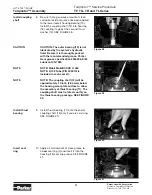
Page 34: ...23 the valve 24 and the second spring 23 into the other end of the valve cavity Turn the second plug 21 with a new o ring 22 loosely into the end cover valve cavity 3 16 inch Allen wrench required SEE FIGURE 52 Assemble relief valve parts in end cover 18 If relief valve components items 21 22 24 were removed from the end cover 2 assemble a new o ring 22 on the two plugs 21 Assemble a two piece rel...

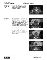
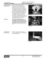
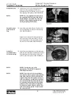
Page 35: ...OTE NOTE If the end cover has a valve 24 use the line you previously scribed on the cover to radially align the end cover into its original position Assemble cover bolts 20 Assemble the 7 special bolts 1 1A 1B or 1C and screw in finger tight Alternately and progressively tighten the bolts to pull the end cover and other components into place with a final torque of 50 55 ft lbs 68 75 N m for the se...

Page 36: ...ed Torque the valve plugs 21 Torque the two shuttle valve plug assemblies 21 in end cover assembly to 9 12 ft lbs 12 16 N m if cover is so equipped SEE FIGURE 59 Torque the two relief valve plug assemblies 21 in end cover assembly to 45 55 ft lbs 61 75 N m if cover is so equipped THE ASSEMBLY OF THE TORQMOTOR IS NOW COMPLETE EXCEPT FOR WOODRUFF KEY 12A NUT 12B WASHER 12C BOLT 12D LOCKWASHER 12E RE...

Page 37: ...ide of the rotor was etched during Torqmotor disassembly this side should be up If the rotor is not etched and does not have a counterbore use the drive link spline contact pattern apparent on the rotor splines to determine the rotor side that must be against the wear plate Assemble vanes CAUTION Assemble full complement of vanes Remove two assembled bolts 4 Assemble six vanes 8C or as many vanes ...

Page 38: ...s into mesh with drive link 10 splines NOTE Use any marking you applied to rotor set components to reassemble the components in their original relationship to ensure ultimate wear life and performance Assemble vanes CAUTION 4 Assemble six vanes 8C or as many vanes that will readily assemble into the stator vane pockets CAUTION Excessive force used to push the rotor vanes into place could shear off...

Page 39: ...eight as the stator half must be reassembled in their respective stator half for the rotor set to function properly Assemble vanes 8 Assemble six vanes 8E or as many vanes that will readily assemble into the stator vane pockets Assemble full complement of vanes 9 Grasp the output end of coupling shaft 12 with locking pliers or other appropriate turning device and rotate coupling shaft drive link a...

Page 40: ...s for counter clockwise coupling shaft rotation Use test stand if available to check operation of the Torqmotor Hydraulic Fluid Keep the hydraulic system filled with one of the following 10W40 SE or SF manufacturers suggested oil Hydraulic fluid as recommended by equipment manufacturer but the viscosity should not drop below 50 SSU or contain less than 125 zinc anti wear additives CAUTION Do not m...

Page 41: ...and correct any external leak in the hydraulic system no matter how minor the leak Comply with manufacturer s specifications for cleaning or replacing the filter CAUTION Do not weld braze solder or any way alter any Torqmotor component CAUTION Maximum operating pressure must not exceed recommended Torqmotor pressure capacity CAUTION Always carefully inspect any system component that may have been ...

Page 42: ...HY13 1527 M1 US Torqmotor Service Procedure TF TG TH and TL Series Parker Hannifin Corporation Hydraulic Pump Motor Division Greeneville TN 37745 US 42 Notes ...

Page 43: ...alf all documents Seller deems necessary to perfect its security interest 11 Improper use and Indemnity Buyer shall indemnify defend and hold Seller harm less from any claim liability damages lawsuits and costs including attorney fees whether for personal injury property damage patent trademark or copyright infringe ment or any other claim brought by or incurred by Buyer Buyer s employees or any o...

Page 44: ...Parker Hannifin Corporation 2745 Snapps Ferry Road Greeneville TN 37745 USA Tel 423 639 8151 FAX 423 787 2418 www parker com pumpmotor ...

Reviews: