


FL20-S Series
20
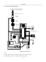
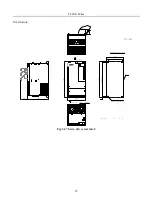
2.1.4 Connection to Peripheral Devices
Three phase AC power (for 1 phase 220v,
only L1 and L3 should be connected)
Breaker
Braking
resistor
Electromagnetic brake relay
(common-open)
EMI filter
Contacter
Input choke
DC choke
Servo Motor
24V power supply
Used to protect power wire
RS 485
communication
interface
MODBUS
PC / PLC
PLC, CNC command
controller
For electromagnetic
brake motor
Encoder interface
( Optional)
( Optional)
(Optional)
( Optional)
*This connection is forbidden for 380V, 3 phase option
Fig 2.1.5 Servo drive system
Note)
For 220V input servo drive, L1C and L2C should be connected to power supply.
For 380V input servo drive, L1C and L2C are forbidden to connect.
Summary of Contents for FL20-S Series
Page 1: ......
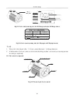
Page 33: ...FL20 S Series 33 M3 structure Fig 3 1 5 Servo drive structure 3 ...
Page 35: ...FL20 S Series 35 M4 structure Approx mass 10 365 kg Fig 3 1 7 Servo drive structure 5 ...
Page 36: ...FL20 S Series 36 M5 structure Approx msaa 11 1Kg Fig 3 1 8 Servo drive structure 6 ...
Page 37: ...FL20 S Series 37 M6 structure Approx mass 17 4Kg Fig 3 1 9 Servo drive structure 7 ...
Page 169: ...FL20 S Series 169 Fig 6 4 44FL20E Cam internal frameworkdiagram ...
Page 347: ...FL20 S Series 347 ...


