FL20-S Series
16
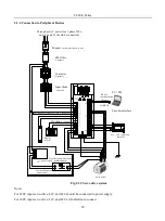
2.1.2 Connection to Peripheral Devices
Charging indicator
The LED will light up when
incoming power is given. The
DC link capacitors will retain
charge for some time. Even if
power is turned off. Do not
touch the power terminals as
long as the LED is ON
Main Circuit terminal
Please refer to Fig 4.1
Control Circuit terminal
Braking resistor terminal
Used to connect resistor.
Please refer to 6.1.7
DC choke terminal
Please refer to Fig 4.1
Servomotor terminal
Operator Panel
Serial communication connector (CN1)
PC,PLC,CNC and other host controller
Please refer to 10.1
.
Encoder connector (CN2)
Please refer to Fig 4.2
I/O signal terminal (CN3)
Ground terminal
Be sure to connect to protect
against electrical shock.
Please refer to Fig 4.1
Please refer to 4.4.2
Please refer to Fig 4.3
Fig 2.1.4 Connection to Peripheral Devices
Summary of Contents for FL20-S Series
Page 1: ......
Page 33: ...FL20 S Series 33 M3 structure Fig 3 1 5 Servo drive structure 3 ...
Page 35: ...FL20 S Series 35 M4 structure Approx mass 10 365 kg Fig 3 1 7 Servo drive structure 5 ...
Page 36: ...FL20 S Series 36 M5 structure Approx msaa 11 1Kg Fig 3 1 8 Servo drive structure 6 ...
Page 37: ...FL20 S Series 37 M6 structure Approx mass 17 4Kg Fig 3 1 9 Servo drive structure 7 ...
Page 169: ...FL20 S Series 169 Fig 6 4 44FL20E Cam internal frameworkdiagram ...
Page 347: ...FL20 S Series 347 ...


