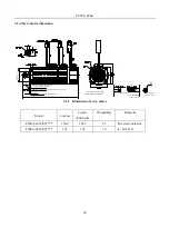


FL20-S Series
51
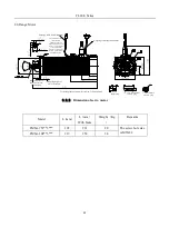
For 380V servo drive
Manual power off Alarm relay
RLY normally
open contact
Contactor KM1
Normally open
contact
KM1
R/L1
S/L2
B2
B3
N
B1
QF circuit breaker
U
V
W
Three- phase AC
380 V power supply
*
PE
M
PG
ALM+
ALM-
+ 24V
0V
Alarm relay
RLY
CN1
CN2
CN3
Contactor
KM 1 coil
Manual power on
External resistor
Servo motor
PE
FIL filter
T/L3
Fig 4-1-5 Typical main circuit wiring of 380V servo drive
Note:
1. Built-in resistor is default and B2 and B3 terminal is short-circuit. If external resistor is used, please remove the
short cable between B2 and B3, and then connect external resistor between B1 and B2.
2. RLY
:
Alarm-signal output relay.
3. KM1: Contactor, connect or disconnect to main circuit power supply through manual switch.
4. N: DC bus.
Note: please connect an emergency stop circuit to main circuit so that servodrive can stop and power
off immediately in case accident occurs.
Summary of Contents for FL20-S Series
Page 1: ......
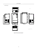
Page 33: ...FL20 S Series 33 M3 structure Fig 3 1 5 Servo drive structure 3 ...
Page 35: ...FL20 S Series 35 M4 structure Approx mass 10 365 kg Fig 3 1 7 Servo drive structure 5 ...
Page 36: ...FL20 S Series 36 M5 structure Approx msaa 11 1Kg Fig 3 1 8 Servo drive structure 6 ...
Page 37: ...FL20 S Series 37 M6 structure Approx mass 17 4Kg Fig 3 1 9 Servo drive structure 7 ...
Page 169: ...FL20 S Series 169 Fig 6 4 44FL20E Cam internal frameworkdiagram ...
Page 347: ...FL20 S Series 347 ...


