FL20-S Series
224
(2)
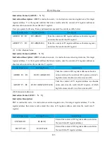
Falling Edge Instruction
Instruction Format: [PLF X Y]
Instruction Description:
PLF is instruction code, X stores the register address of last cyclic state, detect
the falling edge of Y register address; When detecting the falling edge of Y register address, Y register=1
in this cycle, and X register saves last cyclic state.
Table 8.1.29 Rising Edge and Falling Edge Syntax, Results and related Annotations
Syntax Expression
Annotations
PLS B12 B13
When detecting the rising edge of B13 register, B13 register=1 in this cycle and
B12 stores last cyclic state.
PLF B12 B13
When detecting the falling edge of B13 register, B13 register=1 in this cycle and
B12 stores last cyclic state.
(3)
Output Instruction
Instruction Format: [OUT X]
Instruction Description:
OUT is instruction code, X is target register; Output the result of program to X register address;
Syntax Expression
Annotations
OUT B100
Output the result of program to B100 register address
(4)
Main Control Instruction
Instruction Format: [MC]
Instruction Description:
MC is instruction code; If current logic state is valid, the setting address is
valid, so the code between MC and MCR will be in valid status; Otherwise, if current logic state is invalid,
the setting address is invalid, so the code between MC and MCR will be in invalid status;
(5)
Main Control Reset Instruction
Instruction Format: [MCR]
Instruction Description:
MCR is instruction code; same as MC;
(6)
Set Instruction
Instruction Format: [SET X]
Instruction Description:
SET is instruction code, X is target register address; Set the content of X register address as 1;
(7)
Reset Instruction
Instruction Format: [RST X]
Instruction Description:
RST is instruction code, X is target register address; Set the content of B2 register as 0;
(8)
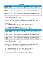
16-bit Absolute Value
Summary of Contents for FL20-S Series
Page 1: ......
Page 33: ...FL20 S Series 33 M3 structure Fig 3 1 5 Servo drive structure 3 ...
Page 35: ...FL20 S Series 35 M4 structure Approx mass 10 365 kg Fig 3 1 7 Servo drive structure 5 ...
Page 36: ...FL20 S Series 36 M5 structure Approx msaa 11 1Kg Fig 3 1 8 Servo drive structure 6 ...
Page 37: ...FL20 S Series 37 M6 structure Approx mass 17 4Kg Fig 3 1 9 Servo drive structure 7 ...
Page 169: ...FL20 S Series 169 Fig 6 4 44FL20E Cam internal frameworkdiagram ...
Page 347: ...FL20 S Series 347 ...


