MSG11-5715-743/EN: AC20F Series - Hardware Installation Manual
MSG11-5715-743/EN 24.04.2023
71 (148)
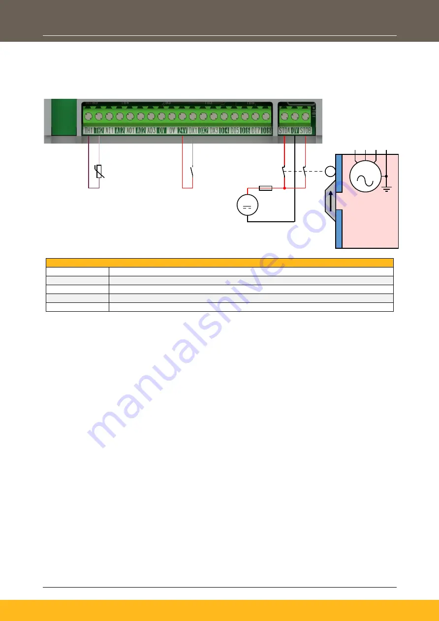
STO Implementation with a Door Switch (Stop Category 0):
This example shows a safety door switch that is used to invoke STO on the drive when the safety door is
‘opened’, allowing access into the ‘Danger Zone’.
The safety door must return to the ‘closed’ position prior to running the drive:
Configuration Setup:
TH1
Motor
Thermistor ‘+’ connection
TH2
Motor Thermistor ‘-’ connection
DX1
Run Forward:
24 V digital input
STOA
Externally fused 24
V input connected via ‘
Safety Door Closed
’ contacts
STOB
Externally fused 24
V input connected via ‘
Safety Door Closed
’ contacts
To run the drive:
1.
Close the ‘Safety Door’ so the contacts and closed circuit (STOA & STOB inputs are supplied with
24 V).
2.
Close the ‘Run Forward’ contact.
To stop the drive:
1.
Open the ‘Run Forward’ contact and wait for the motor to come to a standstill.
To invoke STO:
1.
When the motor is at standstill, open the ‘Safety Door’ so that the contacts are open circuit (no volts
on STOA & STOB inputs).
2.
STO will now be ‘Active’ on the drive, for as long as required.
Note: Opening the ‘Safety Door’ so that the contacts open when the motor is running will result in
the motor coasting to a stop.
The line guiding to the external switches must be separated channel-wise or they must be specially
protected i.e., using shielded cables. A relocation of this wiring is not permitted.
In the example illustrated above, the contacts of the
‘Safety Door’ need to be designed mechanically linked,
in accordance with EN 60947-5-1, annex K.
+24V
M
Safety Door
Closed
DANGER
ZONE
Motor Connections
Back To Power
Stack


