background image

Safe 

Safe 

Safe 

Safe Torque

Torque

Torque

Torque    Off (STO)

Off (STO)

Off (STO)

Off (STO)


07-02-12-02-EN-V1215.doc  /  Type:

 638


89 


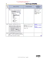
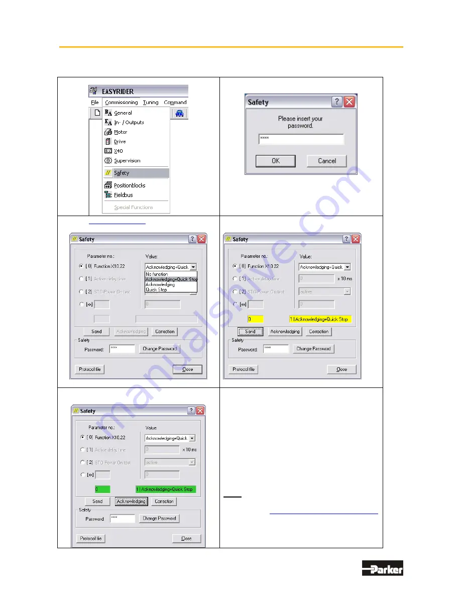
EASYRIDER Safety Parameter Data Entry Dialog Boxes 


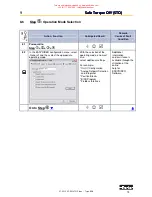
1. Commissioning menu - select “Safety“ : 


2. Access password - enter “BGSM“  


and verify with “OK“  

3. Enter 

Safety Password

, select Parameter 

Nr. and enter the appropriate Value 


4. Send the Parameter - press “Send”one time 


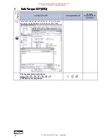
4. When  the yellow display is correct  - press 
the “Acknowledge” button twice to accept 


5. When the parameter display is 

green,

 it 

confirms that the value is correct, has been   
stored and power loss protected in the drive 
unit!  
 
Once all of the relevant safety data 
parameters have been entered, then it is 
possible to call up the protocol form of the 
actual safety parameter settings by pressing 
the “Protocol file” button.  
(ACROBAT Reader is required!) 
 
Note: 
 
A copy of the 

Safety-Parameter-Protocol Form


is available in the appendix of the Servo Drive 
Handbook and can be used for verification 
purposes. 


This manual was downloaded on www.sdsdrives.com 

+44 (0)117 938 1800 - [email protected]

Summary of Contents for 638 series

Page 1: ...638 Series 638 Series 638 Series 638 Series Digital Digital Digital Digital Servo Drive Servo Drive Servo Drive Servo Drive Product Manual This manual was downloaded on www sdsdrives com 44 0 117 938...

Page 2: ...HIPERFACE Feedback System UL 07 05 03 02 Product Manual Bus Interface CAN UL 07 05 04 02 Product Manual Bus Interface Profi Bus DP UL 07 05 07 02 Product Manual I O Interface UL 07 05 08 02 Product M...

Page 3: ...Manual Ballast Resistors Parker Hannifin All rights reserved No portion of this description may be produced or processed in any form without the consent of the company Changes are subject to change wi...

Page 4: ...dback Module X300 24 Feedback Connection X30 SUB D 09 Socket 25 Feedback Module X300 with Memory 27 2 5 Service Interface COM1 RS232 28 2 6 Safe Torque Off 29 Connection Safe Torque Off X11 29 Connect...

Page 5: ...ions 51 Short Circuit Capacity and Discharge Currents 51 5 2 Power Mains Connection 52 Types of power mains 52 Mains supply voltage range 638A 52 Mains supply voltage range 638B 52 Protective Ground C...

Page 6: ...hapter 9 2 2 83 Applications in Accordance with the Regulations 84 Trained Personnel 84 Benefits with the Employment of the Safe Torque Off Function 84 Safety Instructions and Limitations 85 9 2 Safe...

Page 7: ...solver Evaluation Transmitter Principles 114 X30 Endat Evaluation 115 Controller System 115 Mechanical Data 115 12 2 Technical Unit Data 116 638A 116 Output Power 638A 117 Singlephase and Threephase s...

Page 8: ...o motors or other products Therefore we request that you strictly observe our safety and installation instructions Safety Precautions We assume that as an expert you are familiar with and will observe...

Page 9: ...lay or an optical coupler In this way an increased level of protection against potential interference and a limitation of potential damage due to incorrect connections are provided The voltage level m...

Page 10: ...separate the drive completely from the main power connection CAUTION Risk of Electrical Shock Wait 3 minutes after switching the component off to allow the capacitors to discharge Screws sealed with v...

Page 11: ...nal external ballast resistance The AC supply voltage can be directly connected or it can be connected through a transformer as required Important only operated on networks which are grounded at the c...

Page 12: ...em There are 6 operating modes to choose from 0 Seed Current control switchable via Input X10 24 1 Speed control 2 Current control 3 Speed Position control switchable via Input X10 24 4 Position contr...

Page 13: ...e slot A B CAN CAN Bus slot A B CCA 2 x CAN RS 485 slot B A C CC8 2 x CAN 4 outputs and 4 inputs RS 485 slot B A C PDN Profibus DP slot B A IPC8 Profibus DP CAN2 4 outputs and 4 inputs RS 485 slot B A...

Page 14: ...38xxxxFxSTOCCAEAExxx 638xxxxFxSTOCC8000xxx 638xxxxFxSTOCC8EAE xxx 638xxxxFxSTOPDN000xxx 638xxxxFxSTOPDNEAExxx 638xxxxFxSTOPDNCCAxxx 638xxxxFxSTOPDNCC8xxx 638xxxxFxSTOEA5000xxx 638xxxxFxSTOEA5EAExxx 63...

Page 15: ...PC8 C EAE CCA CC8 Motor Feedback System RD2 Standard Resolver D HF2 Option HIPERFACE SC2 Option Sine Cosine with Memorychip as of FW V8 35 RM1 Resolver Memory HM1 HIPERFACE Memory SM11 Sine Cosine Me...

Page 16: ...the device immediately make sure to store it in a dry and clean environment Make sure that the device is not stored near strong heat sources and that no metal chippings can get into the device Dispos...

Page 17: ...Important Please note that on the front side of the unit approximately 70 mm of additional space is required for the signal mating plugs When installing multiple servo drives there is minimum space on...

Page 18: ...44 638B08 638B15 86 64 Important lease note that on the front side of the unit approximately 70 mm of additional space is required for the signal mating plugs When installing multiple servo drives the...

Page 19: ...ons Connection Assignments and Functions 07 02 12 02 EN V1215 doc Type 638 19 2 Connection Assignments and Functions 2 1 Insulation Concept The insulation of the 638 units is achieved in various insul...

Page 20: ...Functions Connection Assignments and Functions Connection Assignments and Functions 20 07 02 12 02 EN V1215 doc Type 638 2 2 Overview of Compact Unit Connections 638A01 to 638A06 This manual was down...

Page 21: ...ction Assignments and Functions Connection Assignments and Functions Connection Assignments and Functions 07 02 12 02 EN V1215 doc Type 638 21 638B03 to 638B15 This manual was downloaded on www sdsdri...

Page 22: ...Ground 638B Plug X60 PIN Designation Function 1 0VP 0 Volt DC Bus 2 RB1 UCC External Ballast Resistor DC Bus 3 RB2 External Ballast Resistor 4 L1 Power Connection 1 400V AC 5 L2 Power Connection 2 40...

Page 23: ...hermo PTC 1 NTC Setup and Wiring example 7 TH Thermo PTC 1 NTC With the connection of the motor temperature sensor at X62 plug you have to change the Temperature supervision parameter in EASYRIDER Men...

Page 24: ...n flexibility and provides for the possibility of future modification 638A 638B Model Type X300 Description Documentation X300_RD2 Resolver Standard X300_HF2 HIPERFACE Option 07 02 09 02 E pdf X300_SC...

Page 25: ...ndard Module Module X300_RD2 X300_RM1 Setup and Wiring example PIN X30 Function 1 2 PTC1 NTC optional 3 cos 4 sin 5 carrier 6 PTC1 NTC optional 7 cos 8 sin 9 carrier 1 With parameter setting PTC can y...

Page 26: ...1 PIN X30 Function 1 GND 2 10 VDC 3 cos 4 sin 5 data 6 7 ref cos 8 ref sin 9 data Sine Cosine Module X300_SC2 or X300_SM1 Module X300_SC2 X300_SM1 PIN X30 Function 1 GND 2 5 5 VDC 3 cos 4 sin 5 zero p...

Page 27: ...638A Attention during the 1st switch on of the control voltage after the X300 module replacement After the replacement of the X300 module make sure that the 1st switch on of the 24V control voltage h...

Page 28: ...32 Function Drive Side RS232 on PC PIN PIN 4 Pin Modular Plug RXD 1 Receive Serial Data 3 TXD TXD 2 Send Serial Data 2 RXD 3 n c not connected GND 4 Ground 5 GND Order code Length Description KnPC637...

Page 29: ...1 3 0V PE Reference Potential 0V 4 STO2 Channel 2 ACTIVE_STO2 5 Ready potential free contact assembly 6 Ready potential free contact assembly Further description of this function can be found in Chap...

Page 30: ...nt Ready 9 Reference Point for Digital Input 0V Reference Point for Digital Inputs 10 Ground for Analog Signal Ground 11 Configurable Operating Mode OPTO Input 12 Configurable Operating Mode OPTO Outp...

Page 31: ...onnected to galvanically insulated terminals Encoder controls Maximum Cable Length connected to ground related terminals other drives controls Maximum Number of Signal Inputs to one as incremental out...

Page 32: ...ly Voltage Output Max 150 mA 5 VDC Pulse resulution Max permissible speed 1024 Incr rpm 12000 rpm 2048 Incr rpm 7600 rpm 4096 Incr rpm 3800 rpm 8192 Incr rpm 1900 rpm 16384 Incr rpm 950 rpm Design Rul...

Page 33: ...ows Software X40 Connection Mode Stepper Motor 2 Pulse INCR I O X40 PIN X40 Function Designation Mode Pulse Direction Mode 2 Pulse 1 Output Drive Active Inverted READY 2 Output Drive Active READY 3 Sh...

Page 34: ...n Incr I O X40 PIN X40 Function Designation 1 Serial Data from SSI Encoder GRAY Code up to 26 Bit Inverted DATA 2 Serial Data from SSI Encoder GRAY Code up to 26 Bit DATA 3 Shield Connector Shield 4 C...

Page 35: ...ent of the Options Modules Pinning for RS232 Module RP 232 PIN Function 1 2 RXD 3 TXD 4 5 GND 485 GND 6 7 8 9 Pinning for RS422 485 Module RP 422 oder RP 485 PIN Function 1 2 3 4 Data In 5 GND 6 Data...

Page 36: ...l 5V 5V 7 8 Line A A 9 with galvanic separation Pinning for EA5 I O Interface Digital In and Outputs Module RP EA5 PIN Function Designation Status 1 BIAS Input 101 Standard Input 2 BIAS Input 102 Stan...

Page 37: ...IN Backward error voltage A DI2 3 Reference Potential IBS GND 4 5 VCCI 5V 6 Data Line OUT Forward error voltage B DO2 7 Data Line IN Backward error voltage B DI2 8 9 Reporting Input RBST for additiona...

Page 38: ...with galvanic isolation Pinning RP 2C8 X120 with I O s X120 Function BIAS PIN Status I O s 0 1 1 BIAS Reset Drive Fault Input 121 Input 2 BIAS Limit Switch Input 122 Input 3 BIAS Limit Switch Input 12...

Page 39: ...nd Functions Connection Assignments and Functions 07 02 12 02 EN V1215 doc Type 638 39 DIP Switch Position for Option Module RP 2CA and RP 2C8 DIP Switch Position CAN DIP Switch Position BUS Terminati...

Page 40: ...IN 5 GND optional 6 Ground 485 CAN GND 7 CAN_H Bus Line dominant high 8 Data OUT 9 Data OUT inv with galvanic isolation Pinning RP CC8 X120 with I O s X120 Function BIAS PIN Status I O s 0 1 1 BIAS R...

Page 41: ...Connection Assignments and Functions Connection Assignments and Functions 07 02 12 02 EN V1215 doc Type 638 41 DIP Switch Position for Option Module RP CCA and RP CC8 DIP Switch Position CAN This manu...

Page 42: ...IN 5 GND optional 6 Ground 485 CAN GND 7 CAN_H Bus Line dominant high 8 Data OUT 9 Data OUT inv Pinning RP PC8 X120 with I O s X120 Function BIAS PIN Status I O s 0 1 1 BIAS Reset Drive Fault Input 1...

Page 43: ...Assignments and Functions 07 02 12 02 EN V1215 doc Type 638 43 DIP Switch Position for Option Module RP PCA PC8 DIP Switch Position CAN2 RS485 and Profibus DP Further information for the Profibus DP...

Page 44: ...Brake Thermo Solid Core and Multiple conductor line 0 14 1 5 0 14 1 5 Flexible with ferrule without plastic sleeve 0 25 1 5 0 25 1 5 Flexible with ferrule with plastic sleeve 0 25 0 5 0 25 0 5 Flexibl...

Page 45: ...18 Switching the operating modes 1 and 2 through input X10 24 Speed control analog Torque controller analog 3 Analog X10 5 18 Digital Simple applications with the requirement of switching between posi...

Page 46: ...2 F6 Input X10 4 F2 F6 F0 F2 F3 F6 Input X10 25 F2 F6 F0 F2 F3 F6 Input X10 11 F1 F1 F1 F1 F1 F2 F6 F0 F1 F2 F3 F6 Input X10 24 F0 L torque H speed control F0 L torque H speed control F1 F2 F6 F1 F2 F...

Page 47: ...ontrol 4 strobe slope 0 1 for BIAS set selection Output X10 12 position reached reference output tracking window exceded synchron format trigger no drive trouble Output X10 13 temperature monitoring r...

Page 48: ...Mode 48 07 02 12 02 EN V1215 doc Type 638 3 4 Functions Diagrams with Protection Mode Switch Off In accordance with EASYRIDER Windows Software Commissioning Motor Motor 30 This manual was downloaded o...

Page 49: ...3 Operating Mode Operating Mode Operating Mode Operating Mode 07 02 12 02 EN V1215 doc Type 638 49 This manual was downloaded on www sdsdrives com 44 0 117 938 1800 info sdsdrives com...

Page 50: ...been installed in an approved enclosure and in accordance with applicable regulations In such an application double check all aspects of the installation Please pay attention during installation of t...

Page 51: ...tors Inspection and certification for the complete installation of servo motors and electronic components must be obtained Grounding Safety Grounding The grounding impedance must meet the requirements...

Page 52: ...range is 3 400 480 AC 10 It is possible to use a lower supply voltage range Note In this case the internal DC BUS capacity may be not high enough and the user has to adjust the undervoltage monitorin...

Page 53: ...rated current of the fuse must be equal to or less than the permissible current carrying capacity of the chosen cross sectional cable IR Icurrent carrying capacity IR Icurrent carrying capacity The fo...

Page 54: ...g How and where is the motor housing grounded Comment High fault currents can occur Extreme unbalance factor of the three phase system When connecting to the power mains short term single or two phase...

Page 55: ...r load on the ballast resistors Increased DC link capacity through smaller residual rippling specifically with single phase applications Increase of the internal ballast peak performance Increase of t...

Page 56: ...stallation Electrical Installation 56 07 02 12 02 EN V1215 doc Type 638 Block Diagram 638A 3 phase Advantage no DC fuses necessary Disadvantage Sum of power limited by line fuse This manual was downlo...

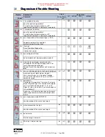
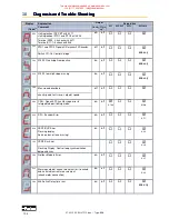
Page 57: ...stallation Electrical Installation 07 02 12 02 EN V1215 doc Type 638 57 Block Diagram 638B 3 phase Advantage no DC fuses necessary Disadvantage Sum of power limited by line fuse This manual was downlo...

Page 58: ...tallation 58 07 02 12 02 EN V1215 doc Type 638 Variation 2 Servo Drives with DC LINK protection Block Diagram 638A 1 phase Advantage Sum of power not limited by line fuse Disadvantage DC fuses necessa...

Page 59: ...stallation Electrical Installation 07 02 12 02 EN V1215 doc Type 638 59 Block Diagram 638A 3 phase Advantage Sum of power not limited by line fuse Disadvantage DC fuses necessary This manual was downl...

Page 60: ...stallation Electrical Installation 60 07 02 12 02 EN V1215 doc Type 638 Block Diagram 638B 3 phase Advantage Sum of power not limited by line fuse Disadvantage DC fuses necessary This manual was downl...

Page 61: ...an be damage the rectifier in the Device In order to protect the rectifier also in the circuit variant 1 mains fuses of the class gRL must be set in These are fuses with combined protection for wires...

Page 62: ...n the units creating a positive energy balancing and overall work load balance of the ballast switches A significant reduction factor in the load can be anticipated depending upon the specifics of the...

Page 63: ...30A Line contactor 4 Type DILM7 DILM7 DILM12 DILM15 DILM15 DC Link connection Fusible cut out VDE DC link resp AC supply 5 Type 10A 30A gRL 10A 30A gRL 10A 30A gRL 16 30A gRL 16A 30A gRL 1 The contin...

Page 64: ...rements is as follows Pmax Pd 59 n1 RPM T tb1 t sec Movement I A Ib t sec Braking Current Values for Example n1 3000 RPM tb1 0 1 sec T 2 0 sec J 0 0005 kgm Total Inertia Definition of Data RL 0 3 Ohm...

Page 65: ...ctivate Electronic Resistance The electronic resistance will be activated Activate Brake Resistor Y Default setting 2 Switching Threshold The switching threshold is to be selected Ucc Brake Resistor O...

Page 66: ...e brake resistor rating through the employment of both the internal and external brake resistor ratings Internal Brake Resistor Rating 20 Watt External Brake Resistor Rating 100 Watt Pext Pint Pges Fo...

Page 67: ...be properly tightened C Use only our filters and cables for motor and resolver connections D Place all wires and cables as close as possible to grounded metal parts E Separate power and control cable...

Page 68: ...ng Instructions Wiring Instructions Wiring Instructions 68 07 02 12 02 EN V1215 doc Type 638 Example for Mounting X61 Motor Connector Wiring This manual was downloaded on www sdsdrives com 44 0 117 93...

Page 69: ...ull up 1 and 3 Analog input X10 19 with internal pull up to 12 V JP1 JP2 Bridged Pad Adjust identically 2 and 3 standard X10 15 high active 1 and 3 X10 15 low active JP3 JP4 Bridged Pad Adjust identic...

Page 70: ...ware Configuration Hardware Configuration 70 07 02 12 02 EN V1215 doc Type 638 Power Board Layout Plan 638A View solder side solder jumper Power Board Layout Plan 638B This manual was downloaded on ww...

Page 71: ...ion Hardware Configuration Hardware Configuration Hardware Configuration 07 02 12 02 EN V1215 doc Type 638 71 Ansicht L tseite L tjumper This manual was downloaded on www sdsdrives com 44 0 117 938 18...

Page 72: ...o security concerns some of the Menus are password protected The set up and start up of the equipment must be carried out by qualified personnel only The installation must be performed taking into con...

Page 73: ...rt EASYRIDER Windows Software EASYRIDER for Windows Software Start side EASYRIDER Software Cable Interface USB RS232 Adapter 1 4 Settings for the Connected COM Ports With the PC in Options Menu select...

Page 74: ...ply is disconnected Eliminate the risk of a short circuit 2 1 3 Check the counter function by looking at the Actual Position Locator Display 1 under the Drive Diagnosis window of the EASYRIDER Softwar...

Page 75: ...ore the specific motor characteristics in the Customer Motor Library 2 2 3 Optionally select temperature sensor Select the temperature sensor connection X30 or X62 in EASYRIDER Default X30 638 X30 Con...

Page 76: ...the absolute measuring device multi turn provider allows for 2 additional parameter settings 1 Selection of the position location per rotation 16 or 20 bit 2 Selection of the absolute position value a...

Page 77: ...Step 3 2 Drive Activation Action Function Anticipated Result Remark Cause of Fault Condition 3 2 1 It is necessary to make additional settings as described in Step 4 2 Optimization Linear Motor when...

Page 78: ...parameters for the control rigidity 4 1 3 Attach the mechanical component with the motor shaft 4 1 4 Perform step 4 1 2 again Pay attention with linear motion The speed generator is controlled by tim...

Page 79: ...u select General and then select the appropriate operating mode With the selection of the operating mode one must also select additional settings For example On Off Configuration Analog Setpoint Selec...

Page 80: ...e interface configuration of the drive If there is not an options board connected then there are no more additional settings required and one can move on to Step 7 6 3 In the configurations menu under...

Page 81: ...p Data Save Action Function Anticipated Result Remark Cause of Fault Condition 7 1 Prerequisite Step 7 2 Read the parameters shown in the EASYRIDER Data Menu under Drive Parameters 7 2 In the Menu und...

Page 82: ...Function Anticipated Result Remark Cause of Fault Condition 7 3 In the Menu under Data select Save As to save the drive parameters on the computer utilizing the file suffix wdd First system start up p...

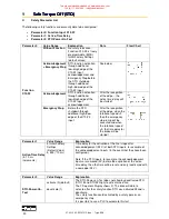
Page 83: ...vements See EN 1037 section 5 3 1 3 The stopping position must not be monitored Should there be the potential of an outside energy source affecting the drive and STO function for example the dropping...

Page 84: ...on issues which are connected to the specifics of the installation must be recognized and taken into consideration as well as appropriate actions to be taken in the event of an emergency Benefits with...

Page 85: ...ctive Braking Phase with Stop Category 1 EN 60204 1 controlled stop with reliable monitored time delay If a fault in the drive system occurs during the active braking phase the axel can coast to a sto...

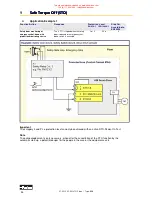
Page 86: ...power component A test takes place to determine the condition of the input channels Within the given window of time the condition of both channels must be identical In the event that a fault conditio...

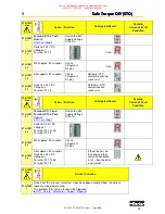
Page 87: ...und STO2 Tolerance ca 20 Sec Active Time Delay tva 0 No additional special functions Diagram Flow chart of the switching status from STO1 and STO2 Note for Standard Operation The STO inputs should alw...

Page 88: ...a through the PC interface follows a specially designed protected procedure including CRC check drive specific password and a double confirmation and acknowledgement process for the parameter values e...

Page 89: ...nowledge button twice to accept 5 When the parameter display is green it confirms that the value is correct has been stored and power loss protected in the drive unit Once all of the relevant safety d...

Page 90: ...er the recognition of the edge when the rotational speed 0 then the emergency stop ramp will be executed and when the rotational speed 0 the time delay for the brake will be started Parameter 1 Value...

Page 91: ...d The drive side initial factory setting of the password is SAFE The responsibility to set the new safety password lies with the operator of the equipment The new safety password should only be shared...

Page 92: ...e Torque Torque Torque Off STO Off STO Off STO Off STO 92 07 02 12 02 EN V1215 doc Type 638 Flow Chart Diagram Function X10 22 Emergency Stop This manual was downloaded on www sdsdrives com 44 0 117 9...

Page 93: ...inputs by switch on the 24V control voltage The drive can not activate if one or both STO inputs have high level The function must configure in the Safety Dialog parameter 2 default Active These mini...

Page 94: ...nitoring switch The STO is tripped when the safety door is opened or emergency shut down switch is activated Cat 3 PL e 0 Important The category 3 and PL e protection level can only be achieved with a...

Page 95: ...PL e 1 Important The category 3 and PL e protection level can only be achieved with an active STO Power On Test Explanation The protection switch unit A1 must be set up with a fail safe time delay as...

Page 96: ...re delivered utilizing two separate channels The wiring layout plan must allow for the physical separation of the wiring channels or incorporate adequate insulation protection and separation Note The...

Page 97: ...ant The category 3 and PL e protection level can only be achieved with an active STO Power On Test Explanation The protection switch unit A1 must be set up with a fail safe time delay as determined an...

Page 98: ...Step 4 STO Test Step 5 STO TEST Step Action Function Anticipated Result Remark Cause of Fault Condition STO TEST 1 1 Prerequisite 1 1 1 Safety Parameter STO Power On Test is Active 1 1 2 Control Volta...

Page 99: ...ST Step Action Function Anticipated Result Remark Cause of Fault Condition STO TEST 4 1 Terminal X11 1 and Terminal X11 4 Test Rebuild STO Test Step 1 Switch the 24V Supply Voltage Off On STO TEST 4 2...

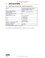
Page 100: ...ow voltage PELV STO Control Voltage Protection 1A Number of Inputs Signal Inputs via Opto Coupler 2 L 0 7 V DC or open H 15 30 V DC Iin at 24VDC 8 mA STO1 L STO activate H STO deactivate STO2 L STO ac...

Page 101: ...ff only if bus interface is integrated 90h deactivated with delay time for the brake deactivated via input on off deactivated via serial command off off 92h Active input is activated with switching on...

Page 102: ...device display immediately after switching on the 24V control supply with 6 no reset the device doesn t boot Reason Resets function defect no Firmware on drive 1 1 E0h chassis shorting and short circu...

Page 103: ...un command 1Eh tracking error with switch off on off only in operation mode position control 20h limit switch 3 on off X10 8 X10 14 X10 14 X10 14 limit switch X10 xx on 0 Volt from Firmware 6 16 08h l...

Page 104: ...op Ramp active on off 638 only 42h X10 22 low high slope missing on off 638 only 2Ah Max speed overload off off check speed limits resp setpoint speed 4Ah CAN Open 402 Sync Message error in Interpolat...

Page 105: ...off off 04h 638 X300 xM Module Memory Error Alteracode missing off off 40h 638 X300 xM Module Memory Error Parameter and BIAS Data missing off off E2h BIAS PLC program command deactivates the drive o...

Page 106: ...Reset with constant repetition of the fieldbus command 0x16 will be works off only once For further processing it is necessary meanwhile to send another control word e g 0 status order 4 Viva 0 1 fla...

Page 107: ...ivating the regulator correctly motor cables interrupted Is input I extern X10 19 activated config menu and not notched up limit switch input activated and not notched up Interference symptoms with po...

Page 108: ...ltage Category IEC 60364 4 443 1999 III Pollution Degree EN 61800 2 4 1 2 1 2 Environmental Conditions General Environmental EN 61800 2 Ambient Temperature Rating Operations Storage Transport IEC 6072...

Page 109: ...necessary 11 2 Conditions of utilization for UL certification 638A Temperature rating of field installed conductors shall be at least 60 C Use copper Conductors only Suitable for use on a circuit capa...

Page 110: ...mends Bussmann LPJ Series or Littlefuse JTD Series The maximum surrounding air temperature is 40 C The drive provides internal motor overload protection This must be set so that 600 of the nominal mot...

Page 111: ...ation See Insulation Concept Signal Inputs and Outputs Connection X10 Additional Galvanic Separation from Power and Control Circuit Nominal Voltage of the In and Outputs 24 V DC Number of Outputs Sign...

Page 112: ...Measurement Range 100 9999Ohm short circuit proof Thermo switch evaluable Thermo Control X62 Galvanic Separation to the Control Circuit Galvanic Separation to the Power Circuit Basic Isolated in acc w...

Page 113: ...L 0 7 V DC or open H 15 30 V DC Iin at 24VDC 8 mA Shortest Time for a Signal to All Inputs to Accept the Signal in an Application 1 ms Damping of the Transfer from Low to High 0 24V default input 200...

Page 114: ...les General The specified data refers to the combination of the standard resolver interface with Function Module X300_RD2 operated with the Resolver R 21 T05 R15 T05 Maximum cable length without usage...

Page 115: ...nt 5V DC 350mA Input resistor sense 20k Ohm In Output signals Driver Type MAX481 or compatible RS422 Differencial Logic Level L 0 5V H 2 5V Differencial Input Level Diff min 0 2V Internal termination...

Page 116: ...utput Sine Voltage with Un Unr Veff 220 Derating of Unr Depending on load or with 1 phase supply Rated Current Efficiency Inr A 1 2 4 6 Max Current Efficiency Time for Imax 1 Imaxr A Sec 2 5 4 5 8 5 1...

Page 117: ...e output voltage is reduced as follows This reduction affects the maximum attainable speed of the applied motor Three phase supply The unloaded output voltage will be reduced to approx 90 maximally 85...

Page 118: ...max 1 Imaxr minimal A Sec 5 5 10 5 15 5 20 5 30 5 Min Motor Inductance 4 75kHz 230V AC Lph ph mH 5 2 5 1 6 1 2 1 2 Min Motor Inductance 4 75kHz 400V AC Lph ph mH 8 9 4 5 3 3 2 2 1 5 Min Motor Inductan...

Page 119: ...in the full load range the limits as shown in the following diagram need to be respected Typical servo applications are not affected by this restriction S3 operation Start Stop At mains voltage 400V...

Page 120: ...12 Technical Data Technical Data Technical Data Technical Data 120 07 02 12 02 EN V1215 doc Type 638 This manual was downloaded on www sdsdrives com 44 0 117 938 1800 info sdsdrives com...

Page 121: ...and commissioning tools Setting of parameters and setting of configurations Servo diagnostics interface diagnostics and fieldbus diagnostics Motor library Save system data in file and load system data...

Page 122: ...ese commands you will be able to program the required machine process in chains of steps The size of a program is limited to a maximum of 1500 BIAS commands The design of the programs occurs with EASY...

Page 123: ...start as of firmware 8 41 Deactive start defines the line number of the first command which is executed first after deactivation or reset with restart of the drive In this case the BIAS interpreter i...

Page 124: ...e during run time Drive type Trajectory cycle 631 635 637 1 899ms 637 637f 638 0 844ms Execute a Mathematics program A 3rd task as math program for supervisory calculation can be started parallel to t...

Page 125: ...X Variable X analogue input Y BIAS Execution pointer const Flag X flag Y flag Z _____________ Variable X variable Y bit Z number Save table Variable X variable Y D_Variable X SQRT D_Variable Y 8 Synch...

Page 126: ...dix Appendix Appendix Appendix 126 07 02 12 02 EN V1215 doc Type 638 14 Appendix 14 1 STO Safety Parameter Report Proposal This manual was downloaded on www sdsdrives com 44 0 117 938 1800 info sdsdri...

Page 127: ...15 Memo Memo Memo Memo 07 02 12 02 EN V1215 doc Type 638 127 15 Memo This manual was downloaded on www sdsdrives com 44 0 117 938 1800 info sdsdrives com...

Page 128: ...ilich Phase V0710 complete 08 03 2010 N Dreilich UL 638 V0911 UL number 638A07 10 10 2011 T Saladin V1014 X10 17 6 Resitorvalue 1 64 Ohm Extension for Fuses UL Class J Class CC 12 5 4 11 08 03 2012 15...

Page 129: ...07 02 12 02 EN V1215 doc Type 638 129 This manual was downloaded on www sdsdrives com 44 0 117 938 1800 info sdsdrives com...

Reviews: