2
Connection Assignments and Functions
Connection Assignments and Functions
Connection Assignments and Functions
Connection Assignments and Functions
32
07-02-12-02-EN-V1215.doc / Type:
638
●
Incremental - Output
EASYRIDER
Windows -
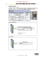
X40 Connection:
Mode = Incremental Output
Incremental encoder simulation for processing in positioning modules
Standard: 1024 increments with Pulse Duty Cycle
Additional selectable pulse settings: 16384, 8192, 4096, 2048, 512, 256, 128, 64
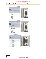
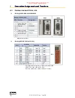
Inc. I/O X40
PIN
X40
Function
Designation
1
Channel B
B
2
Channel B - Inverted
/B
3
Shield Connector
Shield
4
Channel A
A
5
Channel A - Inverted
/A
6
Reference *
GND
7
Channel Z - Inverted Zero Impulse
/Z
8
Channel Z, zero impulse
Z
9
Supply Voltage Output Max. 150 mA
+ 5 VDC
Pulse resulution
Max. permissible speed
≥
1024 Incr./rpm
12000 rpm
2048 Incr./rpm
7600 rpm
4096 Incr./rpm
3800 rpm
8192 Incr./rpm
1900 rpm
16384 Incr./rpm
950 rpm
Design Rule:
The input frequency range of the connected control must equal at least the value
of the pulse output frequency on the X40.
n = max. speed (rpm)
x = increments e.g. 1024
f = output frequency at X40.1,2,4,5
Formula:
[Hz]
=
60
x)
*
(n
*
1,2
=
f
Example:
n = 4000 1/min
Hz
81920
=
60
1024)
*
(4000
*
1,2
=
f
●
Incremental - Input
EASYRIDER
Windows - Software
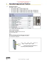
X40 Connection:
Mode = Incremental Input
Parameter range of the input signals: 10...1000000 increments
Figure:
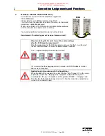
Note:
The operation of incremental encoders via long cables may cause a voltage drop of the encoder
power supply. We recommend the use of a separate voltage supply if necessary.
This manual was downloaded on www.sdsdrives.com
+44 (0)117 938 1800 - [email protected]


