


89
4
●
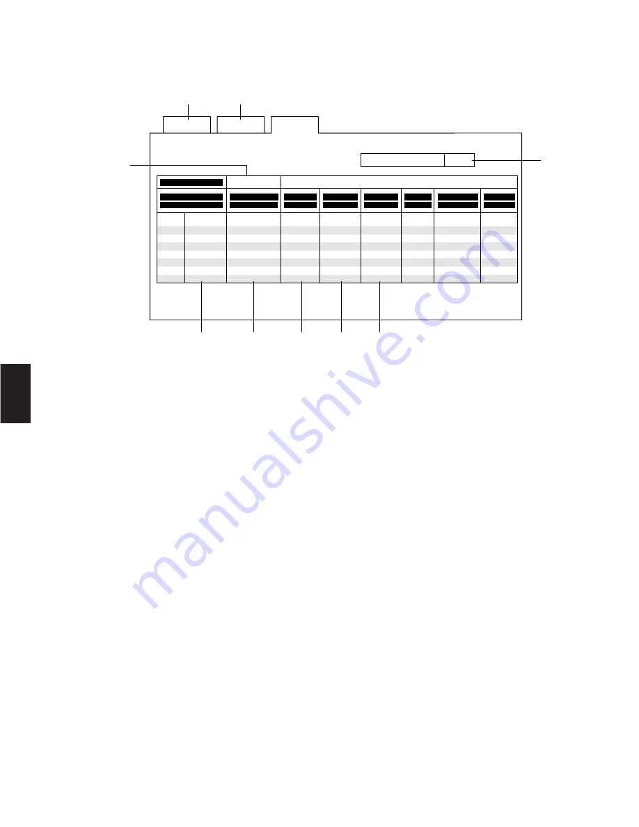
RS-485 Site Communication
This table is used to set the parameters for communication between the Data Boards installed in the Matrix Switcher and the
Camera Site.
To program or edit the RS-485 Communication Table, do the following:
1. Move the cursor to position 3 by moving the Joystick Controller.
Enter the desired data board number (1-8) by pressing the Numeric key, then press the
CAM (SET)
key.
2. Move the cursor to position 4 by moving the Joystick Controller.
Press the Function
F4
Button to open the Pop Up Window. Select Daisy-Chain connection (On) or Home Run Connection
(Off) by moving the Joystick Controller, and then press the
CAM (SET)
key to execute the selection.
3. Move the cursor to position 5 by moving the Joystick Controller.
Enter the desired camera number for site communication by pressing the Numeric keys, and then press the
CAM (SET)
key to execute the selection.
4. Move the cursor to position 6 by moving the Joystick Controller.
Press the Function
F4
button to open the Pop Up Window. Select Full or Half Duplex by moving the Joystick Controller,
and then press the
CAM (SET)
key to execute the selection.
5. Move the cursor to position 7 by moving the Joystick Controller.
Press the Function
F4
Button to open the Pop Up Window. Select the desired Delay Time by moving the Joystick
Controller, and then press the
CAM (SET)
key to execute the selection.
6. Move the cursor to position 8 by moving the Joystick Controller.
Press the Function
F4
button to open the Pop Up Window. Select the desired Baud Rate by moving the Joystick Controller,
and then press the
CAM (SET)
key to execute the selection.
7. Move the cursor to position 9 by moving the Joystick Controller.
Press the Function
F4
button to open the Pop Up Window. Select the desired Wait Time by moving the Joystick Controller,
and then press the
CAM (SET)
key to execute the selection.
8. Repeat the above procedures until the table is completed.
9. When all settings are completed, press the
MON (ESC)
key to escape from the programming mode.
The cursor returns to position 3.
S e t
U p
F 1 : - -
F 2 : - -
F 3 : D E L
F 4 : P o p
S y s t e m
R S - 4 8 5
R S - 4 8 5
S i t e C o m m u n i c a t i o n
# 1
U p
# 2
D a i s y
# 3
# 4
# 5
# 6
# 7
# 8
N u m b e r
F / H
D u p l e x
D e l a y
T i m e
B a u d
R a t e
W a i t
T i m e
0 2
0 4
0 6
1 0
O f f
O f f
1 0 0
O f f
O f f
O f f
O f f
O f f
O f f
O f f
O f f
O f f
O f f
O f f
S t o p
B i t
1
1
1
1
1
1
1
1
P a r i t y
C h e c k
N o n e
N o n e
N o n e
N o n e
N o n e
N o n e
N o n e
N o n e
D a t a
B i t
8
8
8
8
8
8
8
8
W h e n D a i s y M o d e i s " o n " o n l y # 1 w i l l b e a v a i l a b l e
O f f
1 9 2 0 0
9 6 0 0
1 9 2 0 0
1 9 2 0 0
1 2 0 0
1 9 2 0 0
1 9 2 0 0
1 9 2 0 0
F u l l
H a l f
F u l l
F u l l
F u l l
F u l l
F u l l
F u l l
C a m e r a I n
O f f
O f f
B o a r d A d d r . 1
r
q
w
e
t
y
u
i
o
Summary of Contents for WVCU550C - SYSTEM CONTROLLER UNIT
Page 8: ...9 1 SECTION 1 FEATURES OF THE SYSTEM 500 MATRIX SWITCHER ...
Page 19: ...21 2 SECTION 2 DETAILED PRODUCT DESCRIPTION AND SELECTION ...
Page 45: ...47 3 SECTION 3 INSTALLATION AND SYSTEM CONNECTIONS ...
Page 61: ...65 4 SECTION 4 SOFTWARE SETUP ...
Page 90: ...95 5 SECTION 5 OPERATING PROCEDURES ...
Page 122: ...127 6 SECTION 6 TROUBLESHOOTING ...
Page 126: ...131 7 SECTION 7 SPECIFICATIONS ...


