


48
3
INSTALLATIONS
Remove screws.
Side Panel
Palm-rest
Remove Screws.
Rubber
feet
Rack Mount Screws
Rubber
feet
■
WJ-SX550C Matrix Switcher
WJ-AD550 Extension Unit
●
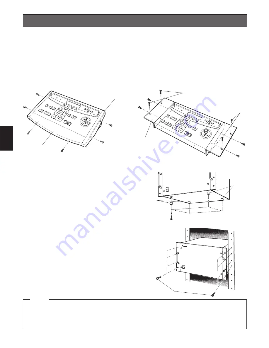
Mounting into the Rack
1. Remove four rubber feet by removing four screws from
the bottom of the Matrix Switcher (Extension Unit).
2. Install the Matrix Switcher (Extension Unit) in the rack
securing it with eight screws (not included).
• The cooling fans inside the Matrix Switcher (or Extension Unit) are subject to wear and need to be replaced periodically.
• Do not block the ventilation opening or slots on the cover to prevent the temperature from rising inside the unit.
Always keep the temperature in the rack within 45˚C (113˚F).
• If the rack is subject to vibration, secure the rear of the unit to the rack using additional mounting brackets (procured
locally).
Cautions
The installation described below should be made by qualified service personnel or system installers and should con-
form to all local codes.
■
WV-CU550C System Controller
●
Replacing the Side Panels with the optional WV-Q62 Rack Mounting Brackets
1. Remove both the left and right side panels of the System Controller by removing four screws.
2. Remove the Palm-rest located on the front of the System Controller by removing two screws.
3. Place the Rack Mounting Brackets on both sides of the System Controller and tighten with the four supplied screws.
4. Install the System Controller with Rack Mounting Brackets in the rack by using four screws (procured locally).
Tighten
screws.
Rack Mounting Bracket
Rack Mount Screws
Rack Mount Screws
Summary of Contents for WVCU550C - SYSTEM CONTROLLER UNIT
Page 8: ...9 1 SECTION 1 FEATURES OF THE SYSTEM 500 MATRIX SWITCHER ...
Page 19: ...21 2 SECTION 2 DETAILED PRODUCT DESCRIPTION AND SELECTION ...
Page 45: ...47 3 SECTION 3 INSTALLATION AND SYSTEM CONNECTIONS ...
Page 61: ...65 4 SECTION 4 SOFTWARE SETUP ...
Page 90: ...95 5 SECTION 5 OPERATING PROCEDURES ...
Page 122: ...127 6 SECTION 6 TROUBLESHOOTING ...
Page 126: ...131 7 SECTION 7 SPECIFICATIONS ...


