background image

ENGLISH - 13

Read this first!

Brazil Only
Brasil Apenas


r

Manuseio de baterias usadas

BRASIL

Após o uso, as pilhas e/ou baterias deverão 

ser entregues ao estabelecimento comercial 

ou rede de assistência técnica autorizada.

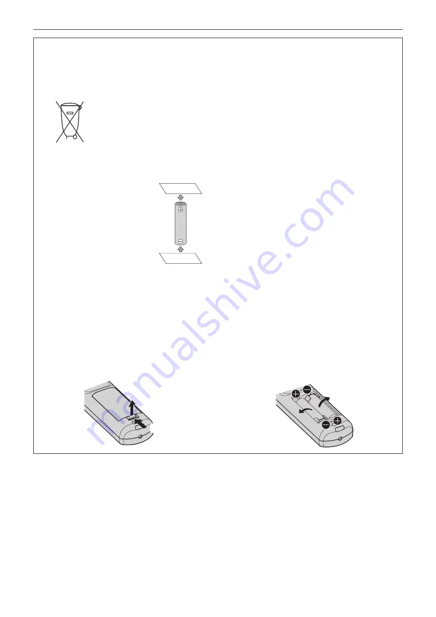
Cobrir os terminais positivo (+) e negativo (-) com uma fita isolante adesiva, antes de depositar numa caixa 

destinada para o recolhimento. O contato entre partes metálicas pode causar vazamentos, gerar calor, romper 

a blindagem e produzir fogo. (Fig. 1)

Fig. 1

Como isolar os terminais

Não desmonte, não remova o invólucro, nem amasse a bateria. O gás liberado pela bateria pode irritar a 

garganta, danificar o lacre do invólucro ou o vazamento provocar calor, ruptura da blindagem e produzir fogo 

devido ao curto circuito dos terminais. Não incinere nem aqueça as baterias, elas não podem ficar expostas a 

temperaturas superiores a 100 °C (212 °F). O gás liberado pela bateria pode irritar a garganta, danificar o lacre 

do invólucro ou o vazamento provocar calor, ruptura da blindagem e produzir fogo devido ao curto circuito dos 

terminais provocado internamente.

Evite o contato com o liquido que vazar das baterias. Caso isto ocorra, lave bem a parte afetada com bastante 

água. Caso haja irritação, consulte um médico.


r

Remoção das baterias

1. Pressione a guia e levante a tampa.

(i)

(ii)

2. Remova as baterias.

Fita Isolante

Fita Isolante

Summary of Contents for PT-RQ32KU

Page 1: ...for India PT RQ32KD z z for other countries or regions PT RQ32K Before operating this product please read the instructions carefully and save this manual for future use Before using this product be su...

Page 2: ...puters 56 Connecting example using DIGITAL LINK 57 Connecting example when using the contrast synchronization function shutter synchronization function 58 Chapter 3 Basic Operations Switching on off t...

Page 3: ...SHUTTER SETTING 139 FREEZE 141 WAVEFORM MONITOR 141 CUT OFF 143 PROJECTOR SETUP menu 144 PROJECTOR ID 144 PROJECTION METHOD 144 LENS 145 OPERATION SETTING 157 LIGHT OUTPUT 159 BRIGHTNESS CONTROL 160...

Page 4: ...ng 229 Self diagnosis display 231 Chapter 7 Appendix Technical information 235 PJLink protocol 235 Using Art Net function 236 Control commands via LAN 242 SERIAL IN SERIAL OUT terminal 245 REMOTE 2 IN...

Page 5: ...ctrician Do not defeat the purpose of the earthing plug WARNING This equipment is compliant with Class A of CISPR32 In a residential environment this equipment may cause radio interference CAUTION To...

Page 6: ...LASER EXPOSITION DIRECTE DANGEREUSE POUR LES YEUX APPAREIL LASER DE CLASSE 3R LONGUEURS D ONDES 448 462nm MAXIMALE DU RAYONNEMENT 333mW 130 TQFX608 DANGER CLASS 4 LASER RADIATION WHEN OPEN AVOID EYE O...

Page 7: ...ype power outlet This is a safety feature If you are unable to insert the plug into the outlet contact an electrician Do not defeat the purpose of the grounding plug Do not remove WARNING USA and Cana...

Page 8: ...le protection against harmful interference when the equipment is operated in a commercial environment This equipment generates uses and can radiate radio frequency energy and if not installed and used...

Page 9: ...coming loose from the wall Fully attach the power connector projector side to the AC IN terminal A power connector that is not completely attached may result in fires caused by electric shocks or heat...

Page 10: ...ealer f f Particular attention must be paid to children Installation work such as mounting the projector on the ceiling should only be carried out by a qualified technician If installation is not carr...

Page 11: ...r injury The projector will be damaged or deformed Do not put your weight on this projector You could fall or the projector could break and injury will result f f Be especially careful not to let youn...

Page 12: ...Do not attach the air filter unit while it is wet Doing so may result in electric shock or malfunctions f f After you clean the air filter units dry them thoroughly before reattaching them Ask your de...

Page 13: ...do pela bateria pode irritar a garganta danificar o lacre do inv lucro ou o vazamento provocar calor ruptura da blindagem e produzir fogo devido ao curto circuito dos terminais N o incinere nem aque a...

Page 14: ...ce f f Art NetTM Designed by and Copyright Artistic Licence Holdings Ltd f f DisplayPort is a trademark or registered trademark of the Video Electronics Standards Association f f Adobe Adobe Flash Pla...

Page 15: ...liability The maintenance cost for long term operation is reduced by the unique light source cooling control technology and improvement of the dust resistance Also it will contribute to the stable ope...

Page 16: ...16 ENGLISH Chapter 1 Preparation This chapter describes things you need to know or check before using the projector...

Page 17: ...alfunctions Follow the operating environment temperature of the projector f f Near high voltage power lines or near motors Doing so may interfere with the operation of the projector f f Places where t...

Page 18: ...vertical and horizontal r rThe geometric adjustment is disabled when projecting an image in simultaneous format The geometric adjustment function cannot be used when the video signal in simultaneous f...

Page 19: ...gagement length 18 mm 23 32 or more tapping depth inside the projector 30 mm 1 3 16 f f Use a torque screwdriver or Allen torque wrench to tighten the fixing screws to their specified tightening torqu...

Page 20: ...ET EMFU330 is attached 500 mm 19 11 16 or longer 500 mm 19 11 16 or longer f f Do not install the projector in a confined space When installing the projector in a confined space provide air conditioni...

Page 21: ...23 32 30 mm 1 3 16 60 or more Security When using this product take safety measures against the following incidents f f Personal information being leaked via this product f f Unauthorized operation of...

Page 22: ...troller and the application software illumination and stage system can be controlled Art Net is made based on DMX512 communication protocol Early Warning Software The projector supports Early Warning...

Page 23: ...temperature becomes the more the luminance of the light source decreases f f The luminance of the light source will decrease by duration of usage If brightness is noticeably reduced and the light sou...

Page 24: ...AYB001052 Power cord DPJA1002ZA for 200 V 240 V DPJA1001ZA for 200 V 240 V DPJA1004ZA for 110 V 120 V Lens hole cover 1 1GE1RZ21K Attached to the product at the time of purchase CD ROM 1 1JK1RQ32KU AA...

Page 25: ...g on the country or region where you purchased the product f f The type and number of the supplied power cords vary depending on the country or region where you purchased the product f f The air filte...

Page 26: ...rminal Board with Audio Model No TY TBN03G it is necessary for the firmware version of the 3G SDI Terminal Board with Audio to be 2 00 or later Consult your dealer regarding the version update to the...

Page 27: ...INPUT MENU button Displays the input selection screen x page 74 12 Input selection buttons DIGITAL LINK DVI D HDMI SLOT 1 SLOT 2 SDI Switches the input signal to project x page 72 DVI D button HDMI bu...

Page 28: ...from the remote control signal receiver The remote control can control at angles of up to 15 vertically and 30 horizontally but the effective control range may be reduced f f If there are any obstacl...

Page 29: ...ty cables 16 AC IN terminal Connect the supplied power cord 17 MAIN POWER switch Turns on off the main power 3 2 1 2 Projection direction Bottom Top WARNING Do not touch the top surface of the project...

Page 30: ...plays the input selection screen x page 74 The indicator of the button is lit while this button is pressed 6 AUTO SETUP button Automatically adjusts the image display position while the image is proje...

Page 31: ...N terminal MULTI PROJECTOR SYNC OUT terminal This terminal is used to connect multiple projectors when balancing the contrast as a combined screen or synchronizing the effects using the shutter functi...

Page 32: ...eous process is not performed even if corresponding signal is input Consult your dealer regarding the version update to the latest firmware For details on how to confirm the firmware version refer to...

Page 33: ...DI HD SDI 3G SDI This is also an active through terminal to output the SDI signal SD SDI HD SDI 3G SDI 6G SDI 12G SDI input to the SDI 1 IN terminal of this board 3 SDI 3 IN terminal This is a termina...

Page 34: ...oard with Audio Model No TY TBN03G The 3G SDI Terminal Board with Audio with the firmware version 2 00 or later has the version displayed on the product The firmware version can also be confirmed in t...

Page 35: ...ID number is assigned to each projector When using the projectors by setting the ID numbers set the ID number of the projector body after initial settings have been completed Then set the ID number of...

Page 36: ...The remote control is effective even in places where an obstacle stands in the light path or where devices are susceptible to outside light Connecting terminals Connecting to a second projector M3 st...

Page 37: ...ENGLISH 37 Chapter 2 Getting Started This chapter describes things you need to do before using the projector such as the setup and connections...

Page 38: ...ut will decrease to approximately 1 3 when using the projector with AC 100 V to AC 120 V f f The supplied power cords vary depending on the country or region where you purchased the product Installati...

Page 39: ...matically detected by setting FLOOR CEILING to AUTO in the PROJECTOR SETUP menu PROJECTION METHOD r r Angle sensor The range of the installation attitude that is detected by the angle sensor built in...

Page 40: ...LE90 x page 41 for details f f Following illustration is prepared on the assumption that the projected image size and position have been aligned to fit full in the screen SD L LW LT L1 L1 L LW LT SW S...

Page 41: ...95 ET D75LE90 is used install the projector so that its back plane is parallel to the screen making the projected image rectangular The vertical keystone distortion in moderate range can be corrected...

Page 42: ...ORIZONTAL KEYSTONE viewed from above Screen Screen Vertical arc correction viewed from the side Horizontal arc correction viewed from above Screen Projection distance Arc radius Screen Projection dist...

Page 43: ...ON used Vertical keystone correction angle Horizontal keystone correction angle Vertical keystone correction angle Horizontal keystone correction angle Min value of R2 L2 Min value of R3 L3 Min value...

Page 44: ...50 59 87 59 81 112 42 10 16 400 5 385 8 616 8 63 10 33 12 09 15 63 15 50 22 52 22 36 43 41 42 88 68 45 68 40 128 53 12 70 500 6 731 10 770 10 80 12 93 15 13 19 56 19 39 28 18 27 98 54 31 53 63 85 60...

Page 45: ...07 70 36 70 32 132 11 12 70 500 6 226 11 069 11 10 13 30 15 56 20 11 19 93 28 97 28 76 55 82 55 13 87 98 87 99 165 23 15 24 600 7 472 13 283 13 33 15 97 18 69 24 16 23 94 34 78 34 54 67 02 66 19 105...

Page 46: ...48 56 77 52 77 50 145 57 12 70 500 7 620 10 160 12 24 14 65 17 15 22 16 21 96 31 92 31 69 61 51 60 75 96 94 96 97 182 05 15 24 600 9 144 12 192 14 69 17 60 20 59 26 62 26 37 38 33 38 06 73 85 72 93 11...

Page 47: ...0 x SD 0 1162 2 15 3 11 1 4 3 1 7361 x SD 0 0832 2 5226 x SD 0 1162 ET D75LE30 2 58 5 00 1 16 10 2 2121 x SD 0 1131 4 2901 x SD 0 1765 2 58 5 00 1 16 9 2 2736 x SD 0 1131 4 4094 x SD 0 1765 3 10 6 01...

Page 48: ...becomes rectangular The adjustable feet can also be used to adjust the projector to be level when it is tilted in the horizontal direction Adjustable feet can be extended by turning them as shown in...

Page 49: ...lt in malfunction f f Do not install the Fixed focus Lens Model No ET D75LE5 production discontinued on the projector Installing by mistake will cause malfunction of the projector f f Panasonic takes...

Page 50: ...the projection lens attached to the projector x page 76 Continue to execute the lens calibration after confirming the LENS TYPE setting x page 76 f f The lens hood needs to be mounted to the projector...

Page 51: ...r storing the projector 3 Attach the supplied lens hole cover Fig 2 f f Insert the lens hole cover by aligning the mark on the lens hole cover E with the mark on the projector E on the left side of LO...

Page 52: ...terface Board refer to Installing the Interface Board optional x page 281 f f Some computer models or graphic cards are not compatible with the projector f f Connect using an extension device etc when...

Page 53: ...x page 33 f f Use a 5C FB or higher such as 5C FB or 7C FB or a Belden 1694A or higher connection cable to properly transmit images Use a connection cable of 100 m 328 1 length or less f f Setting the...

Page 54: ...LOT IN SDI LINK is required when the dual link signal or the quad link signal is input f f To input the dual link signal use the cable with same length and same type for connecting to the SDI 1 IN ter...

Page 55: ...OPTION menu SLOT IN is required depending on the connected external device or the input signal Setting the DISPLAY OPTION menu SLOT IN HDMI LINK is required when the dual link signal or the quad link...

Page 56: ...N 2 DVI D IN 3 DVI D IN 4 terminals can be connected with the HDMI and DVI D compatible device However some external devices may not be able to project images properly such as the image not displaying...

Page 57: ...y not be possible depending on the twisted pair cable transmitter Check the operating instructions of the device to be connected Attention f f Always use one of the following when connecting a VCR g g...

Page 58: ...cturers of which the operation has been verified with the projector visit the Panasonic website https panasonic net cns projector Note that the verification for devices of other manufacturers has been...

Page 59: ...synchronize Note f f The contrast synchronization function and the shutter synchronization function can be used simultaneously f f For details on the settings of the contrast synchronization function...

Page 60: ...60 ENGLISH Chapter 3 Basic Operations This chapter describes basic operations to start with...

Page 61: ...he outlet Note f f The light output will decrease to approximately 1 3 when using the projector with AC 100 V to AC 120 V f f The supplied power cords vary depending on the country or region where you...

Page 62: ...tched off the indicator does not light up even if the power is switched on Turn on the power again after the power indicator ON G STANDBY R lights in red f f The projector consumes power even in stand...

Page 63: ...rature indicator TEMP turns off and the projection starts Refer to When an indicator lights up x page 218 for the indicator status display f f If the operating environment temperature is low and warm...

Page 64: ...TING screen is displayed you can go back to the previous screen Focus adjustment Adjust the focus to display the menu screen clearly You may also need to adjust the zoom and lens shift Refer to Adjust...

Page 65: ...f f For details on each setting item refer to the PROJECTOR SETUP menu OPERATION SETTING 1 Press as to select OPERATING MODE 2 Press qw to switch the item f f The items will switch each time you press...

Page 66: ...13 900 48 000 83 3 63 000 83 3 87 000 83 3 1 The upper limit of the adjustment range is the value described in the MAX LIGHT OUTPUT LEVEL column in the table r r To set the projector based on luminanc...

Page 67: ...Initial setting standby mode Set the operation mode during standby The factory default setting is NORMAL which allows you to use the network function during standby To keep power consumption low duri...

Page 68: ...tting f f The setting will change each time you press the button 16 10 5 7 SCREEN POSITION Set as necessary for the screen in use INITIAL SETTING SET CHANGE MENU SELECT SCREEN FORMAT ENTER 2 Press as...

Page 69: ...n the factory default setting the time zone of the projector is set to 09 00 Japan and Korea Standard Time Change the setting of the PROJECTOR SETUP menu DATE AND TIME TIME ZONE to the time zone of th...

Page 70: ...5 Select the input by pressing the input selection button on the remote control or the control panel f f The buttons that can be used on the remote control or the control panel are as follows Remote c...

Page 71: ...follow the procedures described Failure to do so may damage the internal components and result in malfunctions Note f f For approximately 15 seconds after the projector is switched off the indicator...

Page 72: ...tional Interface Board HDMI Switches the input to HDMI This can be operated when the optional Interface Board equipped with the HDMI input is installed in the slot The input is switched every time the...

Page 73: ...IGITAL LINK The image of the signal input to the DIGITAL LINK LAN terminal is projected SLOT 1 Switches the input to the signal of the optional Interface Board installed in SLOT 1 The input is switche...

Page 74: ...ice is displayed when the ENTER button is pressed while the DIGITAL LINK input is selected in the input selection screen f f If the optional DIGITAL LINK output supported device Model No ET YFB100G ET...

Page 75: ...ens calibration is performed automatically during the next focus adjustment f f If the main power is turned off during the lens shift adjustment a lens calibration error screen is displayed during the...

Page 76: ...on refer to the PROJECTOR SETUP menu LENS LENS TYPE x page 145 Executing the lens calibration Detect the lens adjustment limit value and perform the calibration in the adjustment range Execute the len...

Page 77: ...ress as to select LENS 5 Press the ENTER button f f The LENS screen is displayed 6 Press as to select LENS CALIBRATION 7 Press the ENTER button f f The LENS CALIBRATION screen is displayed 8 Press as...

Page 78: ...f f The home position varies depending on the projection lens type For details refer to Lens shift range x page 79 f f The home position of the Fixed focus Lens Model No ET D75LE95 ET D75LE90 may dev...

Page 79: ...D75LE40 ET D75LE6 Lens shift range Projected image width H Standard projection position Projected image height V 0 29 H 0 29 H 0 15 V 0 15 V 0 59 V 0 59 V Origin position of the lens mounter Projecte...

Page 80: ...been adjusted the lens mounter has focus adjustment screws in three locations f f Tool used Hex driver or Allen wrench diagonal 2 5 mm 3 32 f f The Allen wrench is included with the projection lens ET...

Page 81: ...ted in this state the just focus point is on the inner side of the screen 4 Loosen the fixed screws in the position relative to the location where the focus is shifted the most the location where the...

Page 82: ...s in use shutter closed f f You can set whether to use the mechanical shutter or not and the time for the fade in fade out of the image using the DISPLAY OPTION menu SHUTTER SETTING f f If MECHANICAL...

Page 83: ...IFT x page 100 f f Adjust special signals according to the DISPLAY OPTION menu AUTO SETUP x page 114 f f Automatic adjustment may not work depending on the model of the computer f f Images may be disr...

Page 84: ...test patterns Make sure to display the input signal before performing various adjustments Using the status function Display the status of the projector button 1 Press the STATUS button f f The STATUS...

Page 85: ...single remote control if a unique ID number is assigned to each projector After setting the ID number of the projector set same ID number on the remote control The factory default ID number of the pro...

Page 86: ...86 ENGLISH Chapter 4 Settings This chapter describes the settings and adjustments you can make using the on screen menu...

Page 87: ...LAY LANGUAGE DISPLAY OPTION PROJECTOR SETUP TEST PATTERN SIGNAL LIST SECURITY NETWORK MENU SELECT SUB MENU MULTI DISPLAY ENTER 2 Press as to select an item from the main menu f f The selected item is...

Page 88: ...menu ON SCREEN DISPLAY OSD DESIGN The selected item is displayed with the yellow cursor by the factory default f f In the portrait setting the on screen menu is displayed sideways To display the on s...

Page 89: ...BRIGHTNESS 0 2 93 COLOR 0 2 93 TINT 0 2 93 COLOR TEMPERATURE DEFAULT 2 93 GAMMA DEFAULT 2 95 SYSTEM DAYLIGHT VIEW OFF 2 96 SHARPNESS 8 2 96 NOISE REDUCTION 2 2 97 DYNAMIC CONTRAST 2 2 97 COLOR SPACE...

Page 90: ...LOGO DEFAULT LOGO 137 UNIFORMITY 138 SHUTTER SETTING 139 FREEZE 141 WAVEFORM MONITOR OFF 141 CUT OFF 143 PROJECTOR SETUP Sub menu item Factory default Page PROJECTOR ID ALL 144 PROJECTION METHOD 144 L...

Page 91: ...HANGE 189 NETWORK Sub menu item Factory default Page DIGITAL LINK MODE AUTO 191 DIGITAL LINK STATUS 191 NETWORK SETUP 192 NETWORK CONTROL 192 NETWORK STATUS 193 DIGITAL LINK MENU 193 Art Net SETUP OFF...

Page 92: ...reviation of Digital Imaging and COmmunication in Medicine and is a standard for medical imaging devices Although the DICOM name is used the projector is not a medical device and should not be used fo...

Page 93: ...reen is displayed 3 Press qw to adjust the level Operation Adjustment Range of adjustment Press w Deepens colors 31 31 Press q Weakens colors TINT You can adjust the skin tone in the projected image 1...

Page 94: ...TE BALANCE HIGH screen or the WHITE BALANCE LOW screen is displayed 9 Press as to select RED GREEN or BLUE 10 Press qw to adjust the level Item Operation Adjustment Range of adjustment RED Press w Dee...

Page 95: ...e COLOR TEMPERATURE screen is displayed 5 Press as to select COLOR TEMPERATURE NAME CHANGE 6 Press the ENTER button f f The COLOR TEMPERATURE NAME CHANGE screen is displayed 7 Press asqw to select the...

Page 96: ...s asqw to select the text and press the ENTER button to enter the text 7 Press asqw to select OK and press the ENTER button f f The selected gamma name is changed Note f f When a name is changed displ...

Page 97: ...automatically according to the image to make the contrast optimum for the image 1 Press as to select DYNAMIC CONTRAST 2 Press qw or the ENTER button f f The DYNAMIC CONTRAST individual adjustment scre...

Page 98: ...SYNC x page 169 for details Note f f LIGHTS OUT SIGNAL LEVEL cannot be set when LIGHTS OUT TIMER is set to DISABLE f f When LIGHTS OUT TIMER is set to anything other than DISABLE the following are th...

Page 99: ...ut is installed in SLOT 1 f f The selection item for the input signal to the HDMI IN 3 terminal and the HDMI IN 4 terminal can be selected when the optional Interface Board equipped with the HDMI inpu...

Page 100: ...Vertical up and down adjustment Press a The image position moves up Press s The image position moves down Horizontal right and left adjustment Press w The image position moves to the right Press q Th...

Page 101: ...from the originals Be careful of this when selecting the aspect ratio f f If using the projector in places such as cafes or hotels to display programs for a commercial purpose or for public presentati...

Page 102: ...dot clock frequency exceeding 162 MHz GEOMETRY You can correct various types of distortion in a projected image Unique image processing technology enables projection of a square image on a special sc...

Page 103: ...ntal direction CURVED CORRECTION LENS THROW RATIO Set the throw ratio Select the value close to the actual projection distance divided by projected image width here VERTICAL KEYSTONE HORIZONTAL KEYSTO...

Page 104: ...possible in certain environments f f The optional Upgrade Kit Model No ET UK20 can be used to expand the correctable range To purchase the product consult your dealer f f The GEOMETRY setting is disab...

Page 105: ...PLAY OPTION menu SIMUL INPUT SETTING is set to AUTO x2 speed or AUTO x4 speed and displaying an image in simultaneous format f f The DIGITAL CINEMA REALITY setting is disabled and fixed to OFF when DI...

Page 106: ...G is set to AUTO x2 speed or AUTO x4 speed and displaying an image in simultaneous format EDGE BLENDING The overlapping area is made seamless by creating inclination in the brightness in the overlappe...

Page 107: ...individually if INTERLOCKED is set to OFF 14 Press as to select an item and press qw to adjust the setting f f Once the adjustment is completed press the MENU button to return to the BRIGHTNESS ADJUS...

Page 108: ...page 102 together with the edge blending If NON OVERLAPPED BLACK LEVEL is tilted by correcting the keystone from KEYSTONE in GEOMETRY perform Steps 17 and 18 to adjust the edge blending according to...

Page 109: ...E CREATION setting is disabled and fixed to OFF when FRAME CREATION is set to anything other than OFF and the following setting or operation is performed g g Set FRAME RESPONSE to FAST g g Set the DIS...

Page 110: ...60 1920 x 1200 50 1920 x 1200 60RB g g When the focus test pattern is displayed using the TEST PATTERN menu To enable the QUAD PIXEL DRIVE function while displaying the focus test pattern set QUAD PIX...

Page 111: ...screen display 1 Press as to select the display language and press the ENTER button ENTER DISPLAY LANGUAGE SELECT SET f f Various menus settings adjustment screens control button names etc are display...

Page 112: ...7COLORS WHITE screen is displayed f f By setting AUTO TESTPATTERN to ON the test pattern for the selected color is displayed 6 Press as to select RED GREEN or BLUE 7 Press qw to adjust f f The adjustm...

Page 113: ...f f Before using a colorimeter or similar instrument to measure measurement data set PICTURE MODE to DYNAMIC f f A difference in the color coordinates of target data and measurement values obtained fr...

Page 114: ...items will switch each time you press the button DEFAULT Standard setting WIDE Select this item when an image aspect ratio is a wide screen signal which does not meet the DEFAULT setting 5 Press the E...

Page 115: ...6 SDI3 SLOT2 6 SDI1 2 SDI3 4 2 HDMI1 2 SLOT1 7 HDMI3 4 SLOT2 7 DVI D1 2 SLOT1 7 DVI D3 4 SLOT2 7 SDI1 2 SLOT1 8 SDI3 4 SLOT2 8 SDI1 2 3 4 8 SDI1 2 3 4 SLOT1 2 8 4 SDI1 2 3 4 5 SDI1 2 3 4 SLOT1 5 SDI1...

Page 116: ...ossible to switch to the backup input signal until the original input signal is restored If the input has switched to the backup input automatically it is possible to switch to the backup input signal...

Page 117: ...en if corresponding signal is input Consult your dealer regarding the version update to the latest firmware For details on how to confirm the firmware version refer to How to confirm the firmware vers...

Page 118: ...the projector as standard f f When SDI LINK is set to AUTO use the same format for the signal to be input to the SDI IN 1 SDI IN 2 SDI IN 3 SDI IN 4 terminals If different format signal is input to ev...

Page 119: ...SDI3 4 and press the ENTER button f f The SINGLE LINK SETTING screen or DUAL LINK SETTING screen for the selected item is displayed 5 Press as to select 3G SDI MAPPING 6 Press qw to switch the item f...

Page 120: ...me you press the button AUTO Automatically select 12 bit or 10 bit 12 bit Fixes to 12 bit 10 bit Fixes to 10 bit Setting SIGNAL LEVEL in SDI IN 1 Press as to select SDI IN 2 Press the ENTER button f f...

Page 121: ...w to switch the item f f The items will switch each time you press the button 4K 60p Switches to EDID corresponding to the 4K video signal maximum 4 096 x 2 160 dots maximum vertical scanning frequenc...

Page 122: ...been set depending on your computer or video device SLOT IN Set this item in accordance with the signal input to the input terminal of the installed Interface Board when the optional Interface Board i...

Page 123: ...s The quad link is a setting to display one image with four input signals Dual link HDMI1 HDMI3 HDMI1 HDMI2 HDMI3 HDMI4 HDMI2 HDMI4 Quad link Single link Setting SIGNAL LEVEL in SLOT IN HDMI input 1 P...

Page 124: ...ge is not projected while EDID SELECT is set to 4K 60p SDR or 4K 60p HDR and the 4K video signal is input f f Switch the setting to 2K when proper image is not projected while EDID SELECT is set to 4K...

Page 125: ...on and timing is input in the four inputs of DVI D1 DVI D2 DVI D3 and DVI D4 Selects the dual link when the signal in the same format is input in the DVI D1 input and the DVI D2 input or the DVI D3 in...

Page 126: ...DVI D IN 1 terminal the DVI D IN 2 terminal the DVI D IN 3 terminal or the DVI D IN 4 terminal 16 235 Select this item when the HDMI terminal output from the external device such as Blu ray disc playe...

Page 127: ...f f Select 1024x768p 1280x720p 1280x768p 1280x800p 1280x1024p 1366x768p 1400x1050p 1440x900p 1600x900p 1600x1200p 1680x1050p 1920x1080p 1920x1080i 1920x1200p 1920x2160p 2048x1080p or 2048x2160p 9 Pres...

Page 128: ...and the SDI4 input of the Interface Board to dual link QUAD 2 Sets the SDI1 input the SDI2 input the SDI3 input and the SDI4 input of the Interface Board to quad link 1 This can be selected when the o...

Page 129: ...to select 4K DIVISION 5 Press qw to switch the item f f The items will switch each time you press the button AUTO Automatically select SQUARE or INTERLEAVE SQUARE Fixes the transmission method to Squ...

Page 130: ...H in SLOT IN SDI input 1 Press as to select SLOT IN 2 Press the ENTER button f f The SLOT IN screen is displayed 3 Press as to select SINGLE LINK SETTING DUAL LINK SETTING or QUAD LINK SETTING and pre...

Page 131: ...e SDI 1 IN terminal is output from the SDI 2 IN 1 OUT terminal and the signal input to the SDI 3 IN terminal is output from the SDI 4 IN 3 OUT terminal Note f f The SDI 2 IN 1 OUT terminal and the SDI...

Page 132: ...to Step 5 when DUAL LINK SETTING or QUAD LINK SETTING is selected 4 Press as to select SDI1 SDI2 SDI3 or SDI4 and press the ENTER button f f The SINGLE LINK SETTING screen for the selected item is dis...

Page 133: ...YPE1 LEVEL A or TYPE2 LEVEL B TYPE1 LEVEL A Fixes the mapping method to Type 1 or Level A TYPE2 LEVEL B Fixes the mapping method to Type 2 or Level B Note f f This function does not operate when the S...

Page 134: ...press the button AUTO Automatically selects RGB YPBPR 4 4 4 YPBPR 4 2 2 or XYZ RGB Fixes to RGB YPBPR 4 4 4 Fixes to YPBPR 4 4 4 YPBPR 4 2 2 Fixes to YPBPR 4 2 2 XYZ Fixes to XYZ Setting BIT DEPTH in...

Page 135: ...n OSD 1 Press as to select ON SCREEN DISPLAY 2 Press the ENTER button f f The ON SCREEN DISPLAY screen is displayed 3 Press as to select OSD POSITION 4 Press qw to switch the item f f The items will s...

Page 136: ...es the screen by 90 clockwise COUNTERCLOCKWISE Rotates the screen by 90 counterclockwise Setting OSD DESIGN Set the color of the menu screen OSD 1 Press as to select ON SCREEN DISPLAY 2 Press the ENTE...

Page 137: ...ess the button ON Displays the warning message OFF Hides the warning message Note f f If OFF is set the warning message will not be displayed on the projected image even when warning condition such as...

Page 138: ...ark 127 127 Press q The upper side color becomes pale or the lower side color becomes dark HORIZONTAL Press w The left side color becomes pale or the right side color becomes dark Press q The right si...

Page 139: ...hutter function is used when the operating environment temperature is around 0 C 32 F when MECHANICAL SHUTTER is set to DISABLE Setting FADE IN or FADE OUT Set the image fade in and fade out when the...

Page 140: ...ization function x page 58 1 Press as to select SHUTTER SETTING 2 Press the ENTER button f f The SHUTTER SETTING screen is displayed 3 Press as to select MULTI PROJECTOR SYNC 4 Press the ENTER button...

Page 141: ...set to SLAVE can be operated individually At that time the shutter operation will follow the setting of the DISPLAY OPTION menu SHUTTER SETTING set in that projector FREEZE Pause the projected image t...

Page 142: ...ONTRAST Adjusting red green and blue 1 Set COLOR TEMPERATURE to USER1 or USER2 x page 93 2 Select Select line red on the waveform monitor 3 Adjust dark red areas f f Use RED in WHITE BALANCE LOW to ad...

Page 143: ...ed 1 Press as to select CUT OFF 2 Press the ENTER button f f The CUT OFF screen is displayed 3 Press as to select RED GREEN or BLUE 4 Press qw to switch the item OFF Disables cutoff ON Enables cutoff...

Page 144: ...set to ALL they cannot be controlled separately from the projectors with other ID numbers f f Refer to Setting ID number of the remote control x page 85 for how to set the ID number on the remote con...

Page 145: ...ojector ET D75LE10 Select this item when the Zoom Lens Model No ET D75LE10 is attached to the projector ET D75LE20 Select this item when the Zoom Lens Model No ET D75LE20 is attached to the projector...

Page 146: ...ETTING screen is displayed 5 Press as to select LENS ID 6 Press qw to switch the item f f The items will switch each time you press the button ALL Select this item when the ID number is not to be spec...

Page 147: ...f The LENS screen is displayed 3 Press as to select LENS MEMORY 4 Press the ENTER button f f The LENS MEMORY screen is displayed 5 Press as to select LENS MEMORY SAVE 6 Press the ENTER button f f The...

Page 148: ...zoom position of the loaded lens memory Note f f Lens memory is not guaranteed to be 100 reproduced Readjust the focus zoom and lens shift after loading the lens memory if required f f If the projecti...

Page 149: ...f The name of the saved lens memory and its lens position information VERTICAL POSITION HORIZONTAL POSITION FOCUS POSITION ZOOM POSITION are displayed in the LENS MEMORY NAME CHANGE screen 9 Press as...

Page 150: ...Note following especially when constructing multi display using multiple projectors such as using the edge blending function by setting the ADVANCED MENU menu EDGE BLENDING g g Position of the project...

Page 151: ...turn to the original LIGHT OUTPUT setting value f f After confirming the confirmation message press qw to select NEXT and press the ENTER button The internal focus test pattern of signal level approxi...

Page 152: ...f Wait until the focus is stabilized f f When the Waiting time turns 0s the Please wait message disappears and NEXT becomes selectable 27 Press qw to select NEXT and press the ENTER button f f The SE...

Page 153: ...button SETUP ASSISTANT is cancelled and the FOCUS OFFSET SETUP screen is displayed 11 Wait until Waiting time turns 0s f f Wait until the focus is stabilized f f When the Waiting time turns 0s the Pl...

Page 154: ...ge disappears and NEXT becomes selectable 28 Press qw to select NEXT and press the ENTER button f f The SETUP ASSISTANT screen page 8 8 is displayed f f It will return to previous screen by selecting...

Page 155: ...n 0 Displays the focus test pattern of signal level approximately 0 50 Displays the focus test pattern of signal level approximately 50 100 Displays the focus test pattern of signal level approximatel...

Page 156: ...rectly f f The origin position of the lens mounter and the home position of the projection lens are automatically updated when the lens shift calibration is performed The home position is a origin pos...

Page 157: ...uired The estimated runtime is approximately 20 000 hours Factory default setting LONG LIFE1 1 The luminance will decrease compared to NORMAL but set this item to increase the expected life of the lig...

Page 158: ...etting does not return to factory default setting even if the PROJECTOR SETUP menu INITIALIZE ALL USER DATA is executed Setting LIGHT OUTPUT Adjust the brightness of light source The LIGHT OUTPUT sett...

Page 159: ...0 83 3 65 4 6 300 13 000 83 3 50 0 24 500 83 3 50 0 17 000 9 000 83 3 83 3 34 6 33 900 7 000 83 3 83 3 26 9 46 500 4 000 83 3 83 3 15 4 77 100 1 The upper limit of the adjustment range is the value de...

Page 160: ...TROL screen is displayed 3 Press as to select BRIGHTNESS CONTROL SETUP 4 Press the ENTER button f f The BRIGHTNESS CONTROL SETUP screen is displayed 5 Press as to select CONSTANT MODE 6 Press qw to sw...

Page 161: ...ODE set to AUTO or PC brightness and color cannot be measured Therefore brightness may be corrected approximately two minutes after the shutter function is disabled shutter open f f When the projector...

Page 162: ...set to AUTO and LINK is set to GROUP A through GROUP D The screen shows the status of the brightness control of synchronized projectors up to eight units including the projector being controlled throu...

Page 163: ...1 Multi Monitoring Control Software is included in the supplied CD ROM Note f f If the synchronized projectors are not displayed in the list check the following g g Are there devices with the same IP...

Page 164: ...ECO is set it may take approximately 10 seconds longer before the projector starts projecting after the power is turned on compared with when NORMAL is set f f When NORMAL is set the network function...

Page 165: ...CT 2 Press the ENTER button f f The STARTUP INPUT SELECT screen is displayed 3 Press asqw to select the input and press the ENTER button LAST USED Keeps the input selected last SDI1 Sets the input to...

Page 166: ...TE AND TIME 2 Press the ENTER button f f The DATE AND TIME screen is displayed 3 Press as to select ADJUST CLOCK 4 Press the ENTER button f f The ADJUST CLOCK screen is displayed 5 Press as to select...

Page 167: ...Press as to select the day of week and press qw to select a program number f f You can set the program from No 1 to No 7 indicates that the program number has not been set How to set a program Set up...

Page 168: ...izes luminance Factory default setting LONG LIFE1 Controls the power to increase the life of the light source although the luminance is lower than that of NORMAL LONG LIFE2 Controls the power to incre...

Page 169: ...chanical shutter is not included in the shutter synchronization function f f The menu items in the PROJECTOR SETUP menu MULTI PROJECTOR SYNC are the same as the following setting items g g The PICTURE...

Page 170: ...if MODE is correctly set LINKED All the projectors are correctly connected and correctly set They are in the condition that the contrast synchronization function or the shutter synchronization functio...

Page 171: ...m f f The items will switch each time you press the button 9600 Select the proper speed 19200 38400 7 Press as to select IN PARITY 8 Press qw to switch the item f f The items will switch each time you...

Page 172: ...f f When transferring logos via the optional DIGITAL LINK output supported device Model No ET YFB100G ET YFB200G setting for NO SIGNAL SLEEP of the DIGITAL LINK output supported device should be set t...

Page 173: ...press the button PROJECTOR TYPE Displays the projector type and serial number of the projector PROJECTOR RUNTIME Displays the runtime of the projector LIGHT RUNTIME Displays the runtime of the light...

Page 174: ...the light source with OPERATING MODE set to USER3 CONSOLIDATED RUNTIME 5 Converts the total runtime of the light sources with OPERATING MODE set to each item into the time used with the NORMAL settin...

Page 175: ...runtime is displayed in red 5 CONSOLIDATED RUNTIME can be obtained with the following calculation formula Values obtained by the calculation formula contain a slight error Conversion formula for CONS...

Page 176: ...n the PROJECTOR SETUP menu OPERATION SETTING OPERATING MODE is set to HIGH the recommended time to replace the filter is set to 4 000 hours When the PROJECTOR SETUP menu OPERATION SETTING OPERATING MO...

Page 177: ...projector 1 Press as to select LOAD ALL USER DATA 2 Press the ENTER button f f The SECURITY PASSWORD screen is displayed 3 Enter a security password and press the ENTER button 4 When the confirmation...

Page 178: ...menu LENS ACTIVE FOCUS OPTIMIZER FOCUS OFFSET BRIGHT and FOCUS OFFSET DARK g g FILTER TYPE and FILTER COUNTER in the PROJECTOR SETUP menu FILTER SETTING f f When a projection lens equipped with EEPRO...

Page 179: ...t terminal that can be selected varies depending on the structure of the optional Interface Board installed in the slot 6 Press as to select FRAME LOCK 7 Press qw to switch the item f f The items will...

Page 180: ...PLAY OPTION menu SLOT IN HDMI LINK DVI D LINK SDI LINK is set to anything other than SINGLE f f The setting in the ADVANCED MENU menu FRAME RESPONSE is disabled and fixed to NORMAL while in the four s...

Page 181: ...Displays the menu screen and input signal Built in test patterns are not displayed Note f f Press the ON SCREEN button on the remote control while the test pattern is displayed to hide the menu scree...

Page 182: ...d signal Registered signals can be renamed 1 Press asqw to select the signal of which name is to be changed 2 Press the ENTER button f f The REGISTERED SIGNAL STATUS screen is displayed f f The memory...

Page 183: ...played 3 Press the ENTER button f f The REGISTERED SIGNAL SETUP screen is displayed 4 Press as to select LOCK IN RANGE 5 Press qw to switch the item f f The items will switch each time you press the b...

Page 184: ...currently input is displayed f f The FUNCTION button on the remote control can be used instead of the qw button when SUB MEMORY is selected from the PROJECTOR SETUP menu FUNCTION BUTTON 2 Press asqw t...

Page 185: ...FOCUS ZOOM SHIFT 1 Press as to select SECURITY PASSWORD 2 Press qw to switch the item f f The items will switch each time you press the button OFF Disables the security password entry ON Enables the s...

Page 186: ...tton f f The CONTROL DEVICE SETUP screen is displayed 3 Press as to select CONTROL PANEL or REMOTE CONTROL CONTROL PANEL You can set the limitation on the control from the control panel REMOTE CONTROL...

Page 187: ...n operations DISABLE Disables button operations f f When INPUT SELECT BUTTON is selected in Step 7 the item that can be set varies depending on the selected button Refer to Item that can be set with I...

Page 188: ...tion operation of the DVI D4 input of the Interface Board DISABLE Disables button operations r r HDMI BUTTON HDMI1 SLOT1 and HDMI2 SLOT1 can be selected when the optional Interface Board for HDMI 2 in...

Page 189: ...f the SDI4 input of the Interface Board HDMI1 SLOT1 Fixes to selection operation of the HDMI1 input of the Interface Board HDMI2 SLOT1 Fixes to selection operation of the HDMI2 input of the Interface...

Page 190: ...TER button to enter the text 4 Press asqw to select OK and press the ENTER button f f To cancel select CANCEL Attention f f The initial password is AAAA by the factory default or when ALL USER DATA in...

Page 191: ...gnal that the projector can receive is only up to 1080 60p 1 920 x 1 080 dots dot clock frequency 148 5 MHz f f When the communication method of the twist pair cable transmitter is set to long reach t...

Page 192: ...Art Net SETUP is set to ON 2 X X X or ON 10 X X X NETWORK SETUP cannot be selected NETWORK CONTROL Set up the control method of the network 1 Press as to select NETWORK CONTROL 2 Press the ENTER butt...

Page 193: ...or does not have the RETURN button but the same operation is available with the MENU button Art Net SETUP Make settings to use the Art Net function 1 Press as to select Art Net SETUP 2 Press qw to swi...

Page 194: ...FT Adjusts the lens shift in the vertical direction LENS FOCUS Adjusts the focus LENS ZOOM Adjusts the zoom POWER Controls the power status SHUTTER Controls the shutter FADE IN Sets the fade in time F...

Page 195: ...a channel by itself f f Assign each item of LENS H SHIFT LSB LENS V SHIFT LSB LENS FOCUS LSB and LENS ZOOM LSB to a channel together with LENS H SHIFT MSB LENS V SHIFT MSB LENS FOCUS MSB and LENS ZOO...

Page 196: ...196 ENGLISH Chapter 5 Operations This chapter describes how to use each function...

Page 197: ...s of the display devices projector or flat panel display or the peripheral device within the intranet and to notify the problem or to detect the sign of possible problem of the device can be used Visi...

Page 198: ...cables between the twisted pair cable transmitter and the projector confirm that cable characteristics are compatible with CAT5e or higher using tools such as a cable tester or cable analyzer When a...

Page 199: ...Y 192 168 0 1 DNS1 DNS2 None Operating the computer 1 Turn on the power of the computer 2 Perform the network setting following the instruction of your network administrator f f Operation from the com...

Page 200: ...ltiple systems connected to a network using a computer f f For details of the Crestron ConnectedTM visit the website of Crestron Electronics Inc English only URL http www crestron com Download RoomVie...

Page 201: ...it is not a malfunction f f Screenshot of a computer The size or the display of the screen may be different from this manual depending on the OS or the web browser or the type of computer in use Righ...

Page 202: ...MODE Displays the setting status of OPERATING MODE 6 MAX LIGHT OUTPUT LEVEL Displays the setting status of MAX LIGHT OUTPUT LEVEL 7 SERIAL NUMBER Displays the serial number of the projector 8 REMOTE2...

Page 203: ...ending on the contents of the error 1 2 1 Display of error information Displays the alphanumeric symbols and content of errors warnings that occur Refer to Self diagnosis display x page 231 for the di...

Page 204: ...l page Click Projector control Basic control 1 2 3 4 6 5 1 POWER Turns off on the power 2 SHUTTER Switches the status of the shutter CLOSE Shutter function enabled OPEN Shutter function disabled 3 OSD...

Page 205: ...age The display of the test pattern disappears if Exit is clicked 10 GET OSD Updates the on screen display of the projector at the right of the control page LENS page Click Projector control Detail co...

Page 206: ...ition focus position and zoom position 3 Apply Moves to the lens position displayed in the lens position information field 4 Back Returns to the LENS page Note f f The zoom position is displayed in th...

Page 207: ...AY Enter the default gateway address when not using a DHCP server 6 DNS1 Enter the DNS1 server address Permissible characters for the entry of DNS1 server address primary Numbers 0 9 period Example 19...

Page 208: ...to be set up 5 Date Enter the date to be changed 6 Time Enter the time to be changed 7 Submit Updates the date and time settings Note f f The replacement of the battery inside the projector is requir...

Page 209: ...her E mail will not be sent for 60 minutes after sending the temperature warning E mail even if it reaches the warning temperature 6 INTAKE AIR TEMPERATURE Change the temperature setting for the tempe...

Page 210: ...Internet service provider 2 SMTP Auth Set when the SMTP authentication is selected 3 POP server name Enter the POP server name Allowed characters Alphanumerics A Z a z 0 9 Minus sign and period 4 Use...

Page 211: ...ON 17 00 ON 18 00 ON 19 00 ON 20 00 ON 21 00 ON 22 00 ON 23 00 ON ERROR INFORMATION Error code 00 00 00 00 00 00 00 00 00 00 00 00 00 00 00 00 00 00 00 00 00 00 00 00 00 00 00 00 00 00 00 00 Intake ai...

Page 212: ...ure 28 degC 82 degF Exhaust air temperature 28 degC 82 degF Light1 B temperature 28 degC 82 degF Light1 S temperature 28 degC 82 degF Light2 B temperature 29 degC 84 degF Light2 S temperature 28 degC...

Page 213: ...setting of the password Administrator account 1 3 2 4 1 Account Displays the account to change 2 Current User name Enter the user name before the change Password Enter the current password 3 New User...

Page 214: ...r the desired new password again 4 OK Determines the change of password Note f f To change the account of the Administrator entry of User name and Password in Current is required Crestron Connected TM...

Page 215: ...DI Model No ET MDN12G10 is installed in SLOT 1 or SLOT 2 switching to the SDI2 input or the SDI4 input on the Interface Board for 12G SDI is not possible by operating Input Select Tools page Click Too...

Page 216: ...2 Hours Displays the runtime of the light source 1 and the light source 2 4 Power Status Displays the status of the power 5 Source Displays the selected input 6 Error Status Displays the error status...

Page 217: ...ENGLISH 217 Chapter 6 Maintenance This chapter describes methods of inspection when there are problems maintenance and replacement of the units...

Page 218: ...urce are defective and the light output has decreased f f Turn the MAIN POWER switch to OFF x page 71 and turn on the power again Blinking in red 1 time f f The light source is turned off since the pr...

Page 219: ...nt Filter Unit Model No ET EMF330 is attached Indicator status Status Solution Lighting in red f f The filter is clogged f f The runtime of the filter exceeds the recommended time to replace the filte...

Page 220: ...moke Cut Filter in the following cases x page 278 g g The filter is dirty g g The recommended time to replace the filter has been exceeded f f Remove any objects if they are blocking the air intake ex...

Page 221: ...its surface Handle with care Maintenance of filter The filter indicator FILTER lights up in red in the following cases Perform maintenance of the filter f f The filter is clogged f f The runtime of th...

Page 222: ...Use a Phillips screwdriver to turn the air filter cover fixing screw counterclockwise until it turns freely and open the air filter cover for approximately 90 f f Loosen the air filter cover fixing sc...

Page 223: ...r unit x page 223 next Attention f f After washing the air filter unit dry it thoroughly before attaching it back to the projector Attaching a wet unit will cause an electric shock or malfunction f f...

Page 224: ...n is displayed 3 Press as to select PROJECTOR SETUP 4 Press the ENTER button f f The PROJECTOR SETUP screen is displayed 5 Press as to select FILTER SETTING 6 Press the ENTER button f f The FILTER SET...

Page 225: ...f Take care not to touch the radiator fin etc when removing dirt or dust Performing maintenance of the air filter unit Fig 1 Fig 2 1 Wash the air filter unit Fig 1 i Soak the air filter unit in cold...

Page 226: ...he two air filter units are attached Fig 3 proceed to Attaching the long life filter cover x page 226 next Note f f Make sure that the air filter unit is properly attached before using the projector I...

Page 227: ...ter x pages 61 71 f f Make sure that the projector is stable and perform the maintenance in a safe place even if the filter falls accidentally Note f f The replacement cycle of the air filter unit var...

Page 228: ...ng life filter cover f f Refer to Attaching the air filter unit x page 226 of the Long Life Filter Unit 3 Attach the long life filter cover to the long life filter mount clasp f f Refer to Attaching t...

Page 229: ...rms of light such as fluorescent light affecting the projection 28 f f Is the REMOTE CONTROL setting in CONTROL DEVICE SETUP set to DISABLE 186 f f Is the REMOTE 2 IN terminal used for contact control...

Page 230: ...ET UNIVERSE and START ADDRESS set correctly 193 The DIGITAL LINK input image is not displayed f f Is the cable compatible to the condition of the projector used 57 f f Are the connections between the...

Page 231: ...t source 1 S temperature error 2 U27 Light source 2 B temperature error 2 U28 Light source 2 S temperature error 2 U81 Low AC voltage warning below 90 V 5 U84 DC OUT 1 terminal power supply error 6 U8...

Page 232: ...fan 1 warning 9 FA3 Phosphor wheel fan 1 warning 9 FA4 Phosphor wheel fan 2 warning 9 FA5 Circuit intake fan 1 warning 9 FA6 Circuit intake fan 2 warning 9 FA7 Light source driver fan 1 warning 9 FA8...

Page 233: ...ure 1 Perform maintenance or replacement of the filter x page 221 2 The operating environment temperature is too high Use the projector in an appropriate operating environment temperature 1 3 The oper...

Page 234: ...234 ENGLISH Chapter 7 Appendix This chapter describes the specification of the projector how to install the optional Interface Board and after sales service...

Page 235: ...d returns 0 2 f f 0 No error is detected f f 1 Warning f f 2 Error 2nd byte Indicates light source errors and returns 0 or 2 3rd byte Indicates temperature errors and returns 0 2 4th byte Returns 0 5t...

Page 236: ...is in factory default setting Assignment can be changed Channel Control details 1 2 3 USER CHANNEL1 SHUTTER LIGHT OUTPUT LIGHT OUTPUT LIGHT OUTPUT CHANNEL2 INPUT SELECT INPUT SELECT INPUT SELECT INPUT...

Page 237: ...e standard DC motor unit installed in the Zoom Lens Model No ET D75LE6 ET D75LE8 ET D75LE10 ET D75LE20 ET D75LE30 ET D75LE40 etc is replaced with the stepping motor unit using the Stepping Motor Kit M...

Page 238: ...67 SLOT1 3 3 168 175 SLOT1 4 3 176 183 SLOT2 1 4 184 191 SLOT2 2 4 192 199 SLOT2 3 4 200 207 SLOT2 4 4 208 215 No operation 216 255 1 When the Interface Board equipped with two inputs is installed in...

Page 239: ...7 Lens adjustment Fine adjustment 128 159 Low speed 160 191 High speed 192 223 Execute command action 224 255 r r LENS POSITION Performance Parameter Default value No operation 0 31 0 Move to the home...

Page 240: ...e OFF 0 15 255 0 5s 16 31 1 0s 32 47 1 5s 48 63 2 0s 64 79 2 5s 80 95 3 0s 96 111 3 5s 112 127 4 0s 128 143 5 0s 144 159 7 0s 160 175 10 0s 176 191 No operation 192 255 r r GEOMETRY Performance Parame...

Page 241: ...e Parameter Default value No operation 0 15 0 OFF 16 31 WHITE 32 47 YELLOW 48 63 CYAN 64 79 GREEN 80 95 MAGENTA 96 111 RED 112 127 BLUE 128 143 BLACK 144 159 USER LOGO 160 175 No operation 176 255 r r...

Page 242: ...o Transfer Software included in the supplied CD ROM Control commands via LAN When web control administrator rights password is set Protect mode Connecting 1 Obtain the IP address and port number Initi...

Page 243: ...response String Details Termination symbol Message ERR1 Undefined control command CR 0x0d ERR2 Out of parameter range ERR3 Busy state or no acceptable period ERR4 Timeout or no acceptable period ERR5...

Page 244: ...acquisition command 00QPW CR r r Received data Header Data section Termination symbol Command example 0 0x30 0 0x30 Control command ASCII string CR 0x0d Data length 1 byte 1 byte Undefined length 1 b...

Page 245: ...mmunication cable When connecting using DIGITAL LINK compatible device DIGITAL LINK compatible device Computer D Sub 9p female Projector connecting terminals DIGITAL LINK DIGITAL LINK D Sub 9p male Co...

Page 246: ...ion from the computer starts with STX then the ID command parameter and ETX are sent in this order Add parameters according to the details of control 2 bytes 2 ID characters 2 bytes Semi colon 1 byte...

Page 247: ...n hexadecimal is 03 When multiple projectors are controlled When multiple projectors are all controlled When controlling multiple projectors together via RS 232C perform the following settings 1 Set a...

Page 248: ...1 DV2 1 DVI D2 SLOT1 AU2 DV3 4 DVI D3 SLOT2 AU2 DV4 4 DVI D4 SLOT2 OSH Shutter control 0 OPEN QSH Shutter status query 1 CLOSE VSE Aspect ratio switch 0 DEFAULT 1 4 3 2 16 9 5 THROUGH QSE Aspect ratio...

Page 249: ...GND GND 2 POWER OFF ON 3 SDI1 Other SDI1 4 SDI2 Other SDI2 5 SDI3 Other SDI3 6 SDI4 Other SDI4 7 DIGITAL LINK Other DIGITAL LINK 8 SHUTTER OFF ON 9 ENABLE DISABLE Controlled by remote control Control...

Page 250: ...um of 40 1 Maximum of 45 1 Adjustment range of HORIZONTAL KEYSTONE Maximum of 15 1 Maximum of 40 1 Adjustment range of CURVED CORRECTION Vertical arc Maximum 50 1 Horizontal arc Maximum 50 1 Vertical...

Page 251: ...1080 30p 1 920 x 1 080 33 8 30 0 74 3 l l l 1080 60p 1 920 x 1 080 67 5 60 0 148 5 l l l 1080 50p 1 920 x 1 080 56 3 50 0 148 5 l l l 2K 24p 2 048 x 1 080 27 0 24 0 74 3 l l l 2K 25p 2 048 x 1 080 28...

Page 252: ...68 60 1 280 x 768 47 8 59 9 79 5 l l l 1 280 x 768 5 47 4 60 0 68 3 l l l 1280 x 768 75 1 280 x 768 60 3 74 9 102 3 l l l 1280 x 768 85 1 280 x 768 68 6 84 8 117 5 l l l 1280 x 800 50 1 280 x 800 41 3...

Page 253: ...2 9 50 0 481 6 l 1 This is supported when the optional Interface Board for HDMI 2 input Model No ET MDNHM10 is installed in the slot Quad link is supported only when the optional Interface Board for H...

Page 254: ...l l l l l l l 1080 50p 1 920 x 1 080 56 3 50 0 148 5 l l l l l l l l 2K 24p 2 048 x 1 080 27 0 24 0 74 3 2K 25p 2 048 x 1 080 28 1 25 0 74 3 2K 30p 2 048 x 1 080 33 8 30 0 74 3 2K 48p 2 048 x 1 080 5...

Page 255: ...74 9 102 3 1280 x 768 85 1 280 x 768 68 6 84 8 117 5 1280 x 800 50 1 280 x 800 41 3 50 0 68 0 1280 x 800 60 1 280 x 800 49 7 59 8 83 5 1 280 x 800 6 49 3 59 9 71 0 1280 x 800 75 1 280 x 800 62 8 74 9...

Page 256: ...f f The content of the 4K division column is as follows g g SQ Square transmission format of Square Division g g IL Interleave transmission format of 2 Sample Interleave Division Signal name SIGNAL F...

Page 257: ...vel A RGB 4 4 4 10bit 1 920 x 1 080 28 1 25 0 74 3 3G SDI Level B RGB 4 4 4 10bit 1 920 x 1 080 28 1 25 0 74 3 3G SDI Level A RGB 4 4 4 12bit 1 920 x 1 080 28 1 25 0 74 3 3G SDI Level B RGB 4 4 4 12bi...

Page 258: ...4 4 4 12bit 2 048 x 1 080 28 1 25 0 74 3 3G SDI Level B YPBPR 4 4 4 12bit 2 048 x 1 080 28 1 25 0 74 3 3G SDI Level A RGB 4 4 4 10bit 2 048 x 1 080 28 1 25 0 74 3 3G SDI Level B RGB 4 4 4 10bit 2 048...

Page 259: ...2G SDI Type 1 RGB 4 4 4 12bit 3840 x 2160 30p 3 840 x 2 160 3 67 5 30 0 1 297 0 SQ 6G SDI Type 2 YPBPR 4 2 2 10bit 3 840 x 2 160 3 67 5 30 0 1 297 0 IL 6G SDI Type 2 YPBPR 4 2 2 10bit 3 840 x 2 160 3...

Page 260: ...7 0 IL 6G SDI Type 2 YPBPR 4 2 2 10bit 4 096 x 2 160 3 67 5 30 0 1 297 0 SQ 12G SDI Type 1 YPBPR 4 2 2 12bit 4 096 x 2 160 3 67 5 30 0 1 297 0 IL 12G SDI Type 1 YPBPR 4 2 2 12bit 4 096 x 2 160 3 67 5...

Page 261: ...SDI YPBPR 4 4 4 10bit 1 920 x 1 080i 27 0 48 0 1 74 3 HD SDI YPBPR 4 4 4 12bit 1 920 x 1 080i 27 0 48 0 1 74 3 HD SDI RGB 4 4 4 10bit 1 920 x 1 080i 27 0 48 0 1 74 3 HD SDI RGB 4 4 4 12bit 1080 25p 1...

Page 262: ...2 048 x 1 080 33 8 30 0 1 74 3 HD SDI RGB 4 4 4 12bit 2 048 x 1 080 2 33 8 30 0 1 74 3 HD SDI XYZ 4 4 4 12bit 2K 48p 2 048 x 1 080 2 54 0 48 0 1 148 5 3G SDI Level A YPBPR 4 4 4 10bit 2 048 x 1 080 2...

Page 263: ...3 840 x 2 160 3 56 3 25 0 297 0 IL 6G SDI Type 1 YPBPR 4 4 4 10bit 3 840 x 2 160 3 56 3 25 0 297 0 SQ 6G SDI Type 1 YPBPR 4 4 4 12bit 3 840 x 2 160 3 56 3 25 0 297 0 IL 6G SDI Type 1 YPBPR 4 4 4 12bit...

Page 264: ...25 0 297 0 IL 6G SDI Type 1 YPBPR 4 4 4 12bit 4 096 x 2 160 3 56 3 25 0 297 0 SQ 6G SDI Type 1 RGB 4 4 4 10bit 4 096 x 2 160 3 56 3 25 0 297 0 IL 6G SDI Type 1 RGB 4 4 4 10bit 4 096 x 2 160 3 56 3 25...

Page 265: ...4 4 4 10bit 3 840 x 2 160 54 0 24 0 1 297 0 SQ 3G SDI Level A YPBPR 4 4 4 12bit 3 840 x 2 160 54 0 24 0 1 297 0 IL 3G SDI Level A YPBPR 4 4 4 12bit 3 840 x 2 160 54 0 24 0 1 297 0 SQ 3G SDI Level B Y...

Page 266: ...B YPBPR 4 2 2 12bit 3 840 x 2 160 56 3 50 0 297 0 SQ 3G SDI Level A YPBPR 4 4 4 10bit 3 840 x 2 160 56 3 50 0 297 0 SQ 3G SDI Level B YPBPR 4 4 4 10bit 3 840 x 2 160 56 3 50 0 297 0 SQ 3G SDI Level A...

Page 267: ...PBPR 4 2 2 10bit 3 840 x 2 160 112 5 50 0 594 0 SQ 3G SDI Level B YPBPR 4 2 2 10bit 3 840 x 2 160 112 5 50 0 594 0 IL 3G SDI Level B YPBPR 4 2 2 10bit 4096 x 2160 24p 4 096 x 2 160 54 0 24 0 1 297 0 S...

Page 268: ...96 x 2 160 67 5 30 0 1 297 0 IL 3G SDI Level A YPBPR 4 2 2 12bit 4 096 x 2 160 67 5 30 0 1 297 0 SQ 3G SDI Level B YPBPR 4 2 2 12bit 4 096 x 2 160 67 5 30 0 1 297 0 IL 3G SDI Level B YPBPR 4 2 2 12bit...

Page 269: ...rted when the optional Interface Board for DVI D 2 input Model No ET MDNDV10 is installed in the slot 3 In addition to the standard SDI input this supports the input of the optional 3G SDI Terminal Bo...

Page 270: ...ted metal and molded plastic Dimensions Width 700 mm 27 9 16 Height 418 mm 16 15 32 with the feet at shortest position 373 mm 14 11 16 excluding the feet 370 mm 14 9 16 excluding the feet and protrusi...

Page 271: ...rs of accessories and optional accessories are subject to change without prior notice r r Connecting terminal slot SDI IN 1 terminal SDI IN 2 terminal SDI IN 3 terminal SDI IN 4 terminal Total 4 sets...

Page 272: ...cy 27 0 MHz only 3 This is supported when the optional Interface Board for HDMI 2 input Model No ET MDNHM10 is installed in the slot 4 This is supported when the optional Interface Board for DVI D 2 i...

Page 273: ...73 Dimensions Unit mm 290 11 13 32 350 13 25 32 700 27 9 16 951 37 7 16 580 22 27 32 45 1 25 32 245 5 9 21 32 373 14 11 16 418 16 15 32 25 31 32 90 3 17 32 1 070 42 1 8 1 249 2 49 3 16 Actual dimensio...

Page 274: ...7 Appendix Dimensions 274 ENGLISH r r When the optional Long Life Filter Unit Model No ET EMFU330 is attached 290 11 13 32 112 2 4 13 32 700 27 9 16 580 22 27 32 258 9 10 3 16 25 6 1 335 8 13 7 32 73...

Page 275: ...Air filter unit Tabs on the projector body d Tabs on the projector body c Air filter cover fixing screw Air filter unit compartment and the projector s air intake port 1 Turn off the power of the pro...

Page 276: ...unt clasp fixing screw M4 x 10 supplied with the Long Life Filter Unit optional f f When the long life filter mount clasp is attached proceed to Attaching the air filter unit x page 276 next Attaching...

Page 277: ...button on the remote control or control panel f f The MAIN MENU screen is displayed 3 Press as to select PROJECTOR SETUP 4 Press the ENTER button f f The PROJECTOR SETUP screen is displayed 5 Press as...

Page 278: ...to the projector Grip on the air filter unit b Grip on the air filter unit a Fig 3 Fig 2 Fig 1 Air filter cover Air filter unit Tabs on the projector body d Tabs on the projector body c Air filter cov...

Page 279: ...ment of the projector body c Fig 2 f f Confirm that the tabs on the air filter unit compartment Smoke Cut Filter compartment c and d are hooked to the Smoke Cut Filter frame 2 Slide the air filter cov...

Page 280: ...OPERATION SETTING OPERATING MODE is set to LONG LIFE1 LONG LIFE2 or LONG LIFE3 Set OPERATING MODE to anything other than LONG LIFE1 LONG LIFE2 or LONG LIFE3 when using the Smoke Cut Filter f f Continu...

Page 281: ...the slot insert it into the connector straight and slowly g g It may not operate or cause malfunction if it is not correctly installed f f To use the 3G SDI Terminal Board with Audio Model No TY TBN0...

Page 282: ...rotating counterclockwise with a Phillips screwdriver The removed screws are used to fix the slot cover f f Hold the handle of the Interface Board and remove it slowly 2 Attach the slot cover f f Att...

Page 283: ...Light source indicator 218 LIGHT switch Projector body 30 List of compatible signals 251 LOAD ALL USER DATA 177 LOCK button Remote control 27 Long Life Filter Unit 224 228 275 M Main menu 88 Main pow...

Page 284: ...rature indicator 218 TEST PATTERN 91 181 TEST PATTERN button Remote control 27 84 TEXT CHANGE 186 TINT 93 Troubleshooting 229 U UNIFORMITY 138 Upgrade Kit 250 W WAVEFORM MONITOR 141 Z ZOOM 101 ZOOM bu...

Page 285: ...ropean Union If you wish to discard these items please contact your local authorities or dealer and ask for the correct method of disposal Product Information for Turkey only AEEE Y netmeli ine Uygund...

Reviews: