background image

Technical information

ENGLISH - 109

Appendix

z

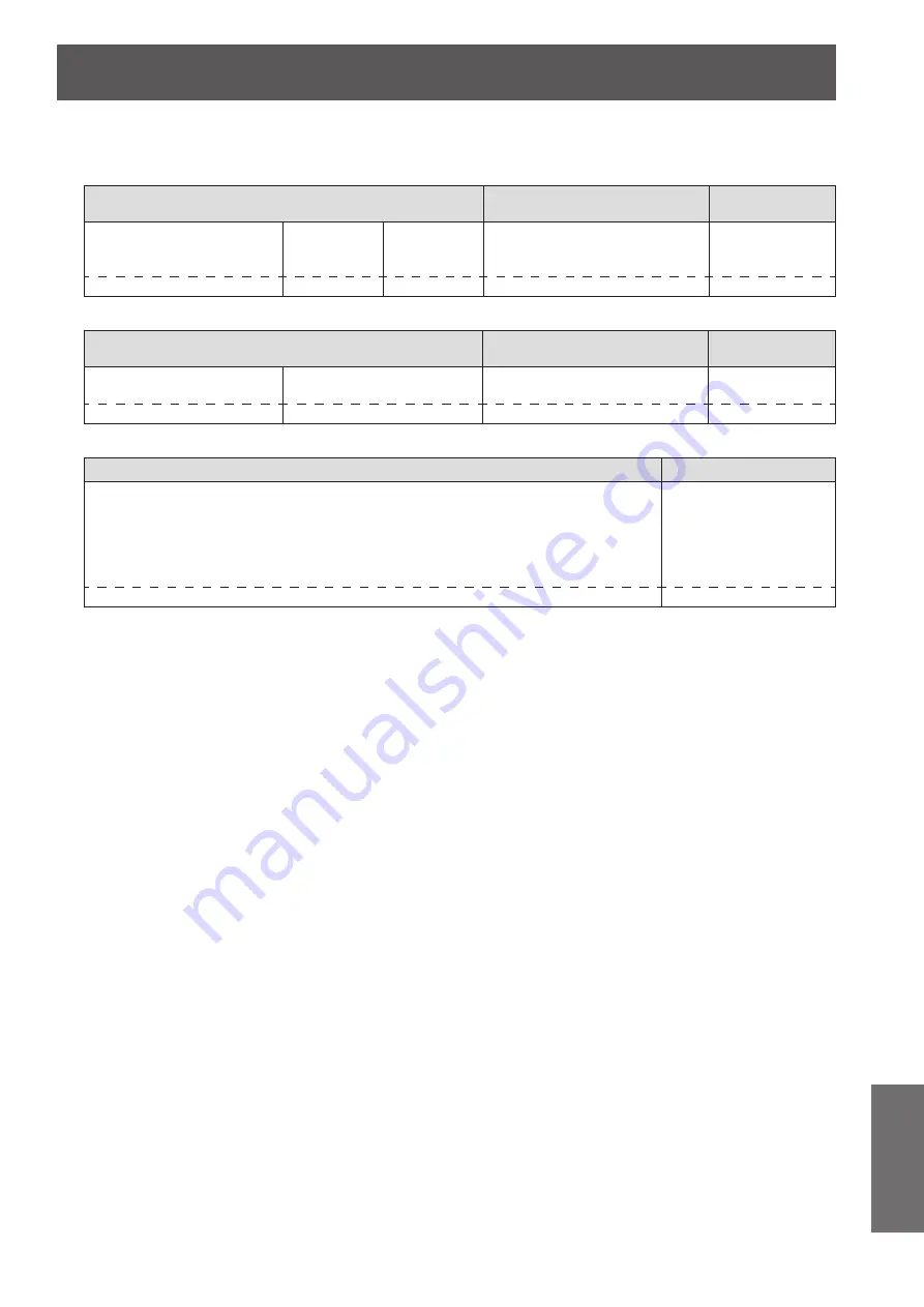
Command transmission method

Transmit using the following command formats.

Transmitted data

Header

Data section

Termination 

symbol

Hash value

(“Connection method” 

(

 page 108))

‘0’

0x30

‘0’

0x30

Control command

(ASCII string)

(CR)

0x0d

32 bytes

1 byte

1 byte

Undefined length

1 byte

Received data

Header

Data section

Termination 

symbol

‘0’

0x30

‘0’

0x30

Control command

(ASCII string)

(CR)

0x0d

1 byte

1 byte

Undefined length

1 byte

Error response

Error message

Termination symbol

“ERR1” 

Undefined control command

“ERR2” 

Out of parameter range

“ERR3” 

Busy state or no-acceptable period

“ERR4” 

Timeout or no-acceptable period

“ERR5” 

Wrong data length

“ERRA” 

Password mismatch

(CR)

0x0d

4 bytes

1 byte

Summary of Contents for PT-LZ370E

Page 1: ...this product please read the instructions carefully and save this manual for future use Before using your projector be sure to read Read this first pages 2 to 8 Model No PT LZ370E TQBJ0412 LCD Projector Commercial Use Operating Instructions Functional Manual ENGLISH ...

Page 2: ...ng pin on the mains plug This apparatus is equipped with a three prong earthingtype mains plug This plug will only fit an earthing type mains socket This is a safety feature If you are unable to insert the plug into the mains socket contact an electrician Do not defeat the purpose of the earthing plug CAUTION To assure continued compliance follow the attached installation instructions which includ...

Page 3: ...wall outlets which are coming loose from the wall Do not use anything other than the provided power cord Failure to observe this will result in electric shocks or fire Clean the power plug regularly to prevent it from becoming covered in dust Failure to observe this will cause a fire z z If dust builds up on the power plug the resulting humidity can damage the insulation z z If not using the proje...

Page 4: ... High voltages can cause fire or electric shocks z z For any inspection adjustment and repair work please contact an Authorized Service Center Do not project an image with the lens cover attached Doing so can cause fire Do not allow metal objects flammable objects or liquids to enter inside of the projector Do not allow the projector to get wet Doing so may cause short circuits or overheating and ...

Page 5: ...se batteries with the outer cover peeling away or removed If the battery fluid leaks do not touch it with bare hands and take the following measures if necessary z z Battery fluid on your skin or clothing could result in skin inflammation or injury Rinse with clean water and seek medical advice immediately z z Battery fluid coming in contact with your eyes could result in loss of sight In this cas...

Page 6: ...locations exposed to direct sunlight or near stoves Always disconnect all cables before moving the projector Moving the projector with cables still attached can damage the cables which will cause fire or electric shocks to occur ACCESSORIES Do not use the old lamp unit If used it could cause lamp explosion If the lamp has broken ventilate the room immediately Do not touch or bring your face close ...

Page 7: ...Read this first ENGLISH 7 Important Information To remove the battery Remote Control Battery 1 Press the guide and lift the cover i ii 2 Remove the batteries ...

Page 8: ... Standards Association RoomView Crestron RoomView and Crestron Connected are trademarks of Crestron Electronics Inc The font used in the on screen displays is a Ricoh bitmap font which is manufactured and sold by Ricoh Company Ltd Adobe Flash Player is either a trademark or registered trademark of Adobe Systems Incorporated in the United States and or other countries Other names company names or p...

Page 9: ...h on the power for the first time after purchase Features of the Projector Features of the Projector The 2x zoom lens and the lens shift allow more flexible setup of the projector A new lamp and optical system have been introduced to improve color reproducibility and contrast This projector is equipped with technology to automatically adjust the image according to the lighting of the projection en...

Page 10: ...ng 37 Selecting the input signal 37 Adjusting the image 37 Remote control operation 39 Using the AV mute function 39 Using the Freeze function 39 Switching the input 40 Using the Automatic setup function 40 Using the Function button 41 Using the ECO management function 41 Resetting to the factory default 41 Adjusting the volume 41 Settings Menu navigation 42 Navigating through the menu 42 Main men...

Page 11: ... 76 WIRED LAN 76 NAME CHANGE 76 NETWORK CONTROL 77 STATUS 77 INITIALIZE 77 Network connections 78 Required environment for computer connection 78 Network settings of computer 79 Accessing from the Web browser 79 Maintenance LAMP and TEMP indicators 95 Managing the indicated problems 95 Maintenance replacement 97 Before maintaining replacing the unit 97 Maintenance 97 Replacing the unit 99 Troubles...

Page 12: ...rd the front of the projector z z Near lights studio lamps etc where temperature changes greatly Operating environment page 117 Doing so may shorten the life of the lamp or result in deformation of the outer case and malfunctions z z Near high voltage power lines or near motors Doing so may interfere with the operation of the projector Be sure to ask a specialized technician when installing the pr...

Page 13: ...oise and connect wired LAN again z z In rare cases communication via LAN may not be possible due to static electricity or noise In such cases press the power button on the remote control or control panel to turn off the power of the projector After the cooling fan is stopped after the power indicator ON G STANDBY R of the projector body that is illuminating orange changes the indication to illumin...

Page 14: ...oduct z z Unauthorized operation of this product by a malicious third party z z Interfering or stopping of this product by a malicious third party Take sufficient security measures page 73 z z Make your password as difficult to guess as possible z z Change your password periodically z z Panasonic Corporation or its affiliate company never inquires a password directly to a customer Do not tell your...

Page 15: ...or more details please consult your dealer Lamp The luminous source of the projector is a mercury lamp with high internal pressure A high pressure mercury lamp has following characteristics z z The brightness of the lamp will decrease by duration of usage z z The lamp may burst with sound or shorten life by shock or chipping z z The life of the lamp varies greatly depending on individual specifici...

Page 16: ...ached to the projector at the time of purchase Attention z z After unpacking the projector discard the power cord cap and packaging material properly z z For lost accessories consult your dealer z z The part numbers of accessories and separately sold components are subject to change without notice z z Store small parts in an appropriate manner and keep them away from young children z z Store the l...

Page 17: ...ntained in the CD ROM and their restrictions z zSoftware license GNU GENERAL PUBLIC LICENSE GNU LESSER GENERAL PUBLIC LICENSE z z Multi Projector Monitoring Control Software Windows This software allows you to monitor and control multiple projectors connected to the LAN z zLogo Transfer Software Windows This software allows you to create original images such as company logos to be displayed when p...

Page 18: ...ECTION METHOD and HIGH ALTITUDE MODE 1 Press to select an item 2 Press to switch the setting INITIAL SETTING SWITCH TO HIGH ALTITUDE MODE ON IF OVER 1400m 4593Ft PROJECTION METHOD RETURN HIGH ALTITUDE MODE OFF FRONT DESK ENTER SELECT z z PROJECTION METHOD page 65 FRONT DESK Setting on a desk etc in front of the screen FRONT CEILING Mounting on a ceiling using the ceiling mount bracket optional in ...

Page 19: ...ton ENTER button Used to operate the menu screen Also used to enter the password for SECURITY or to enter characters 12 AV MUTE button Used to temporarily turn off the image and sound page 39 13 ECO button Displays the setting screen for the ECO management page 41 14 VOLUME VOLUME button Adjusts the volume of the audio output page 41 15 Remote control signal transmitter 16 Strap hole Attach a stra...

Page 20: ... 6 Zoom ring Adjusts zoom 7 Air intake port 8 Air filter cover There is an air filter unit inside page 97 9 Air exhaust port 10 Remote control signal receiver 11 Projection lens 12 Lens shift lever Adjusts lens shift 13 Control panel page 21 14 Lens shift cover 15 Connecting terminals page 21 16 Security slot This security slot is compatible with the Kensington security cables 17 AC IN terminal Co...

Page 21: ...network 2 HDMI IN 1 HDMI IN 2 terminals This is a terminal to input the HDMI signal 3 COMPUTER IN terminal This is a terminal to input the RGB signal or the YCBCR YPBPR signal 4 SERIAL terminal This is a RS 232C compatible terminal to externally control the projector by connecting a computer 5 COMPONENT IN terminal This is a terminal to input the YCBCR signal or the YPBPR signal 6 VIDEO IN termina...

Page 22: ...he projector you can control the projector by pressing the ID ALL button How to set 1 Press the ID SET button on the remote control 2 Within five seconds press the one digit ID number set on the projector using the number 1 6 buttons z z If you press the ID ALL button you can operate the projectors regardless the setting of the projectors ID numbers Attention z z Since setting of the ID number on ...

Page 23: ...ranslucent screen Menu item 1 Method PROJECTION METHOD REAR CEILING Menu item 1 Method PROJECTION METHOD REAR DESK 1 For details of the menu items confirm from the PROJECTOR SETUP menu PROJECTION METHOD page 65 Parts for ceiling mount optional You can install the projector on the ceiling using the optional ceiling mount bracket ET PKA110H for high ceilings ET PKA110S for low ceilings z z Use only ...

Page 24: ...e screen aspect ratio is 16 9 All measurements below are approximate and may differ slightly from the actual measurements unit m Image diagonal size SD Projection distance L Distance from the center of lens to the image lower end H Minimum projection distance LW Maximum projection distance LT 1 02 40 1 11 3 8 2 29 7 6 0 08 0 58 1 27 50 1 41 4 8 2 87 9 5 0 09 0 71 1 52 60 1 70 5 7 3 46 11 4 0 11 0 ...

Page 25: ...0 23 4 0 05 1 57 3 05 120 4 24 13 11 8 53 28 0 0 05 1 88 3 81 150 5 32 17 5 10 67 35 0 0 07 2 36 5 08 200 7 11 23 4 14 24 46 9 0 09 3 14 6 35 250 8 90 29 2 17 81 58 5 0 12 3 93 7 62 300 10 69 35 1 21 38 70 2 0 15 4 72 Projection distance calculation formula You can calculate projection dimensions from the projection screen size SD m using the formula below The unit of the formula is m All values o...

Page 26: ...etracted by turning it in the reverse direction Adjustable range Adjustable feet 16 mm 5 8 Attention z z Heated air is expelled from the air exhaust port Do not touch the air exhaust port directly when adjusting the adjustable feet page 20 Note z z Tighten the adjustable feet until you hear them click into place Lens shift and positioning If the projector is not positioned right in front of the ce...

Page 27: ...in direction A Move the lens shift lever in direction B z z When adjusting the vertical position move the lens shift lever vertically Move the lens shift lever in direction D Move the lens shift lever in direction C Screen Up to approx 65 of the projection screen Up to approx 65 of the projection screen Attention z z Do not force the lens shift lever If excessive force is placed on the lever it ma...

Page 28: ... adjusted within the following range Refer to Screen size and throw distance page 24 for the projection screen height SH and width SW z zProjector setting range when the screen position is fixed Projector Projector setting range center of lens Center of lens Screen Vertical center of screen ...

Page 29: ...optimum projection image quality z z When the lens shift lever is at the horizontal limit of the shift range you cannot move the lever to the vertical limit Likewise when the lens shift lever is at the vertical limit of the shift range you cannot move the lever to the horizontal limit z z The focus may change when the lens position is shifted out of the adjustment range This is because the movemen...

Page 30: ...rector TBC must be connected z z The projector accepts video signals S video signals analog RGB signals with TTL sync Level and digital signals z z Some computer models are not compatible with the projector z z Refer to List of compatible signals page 114 for the types of video signals that can be used with the projector S VIDEO IN terminal pin assignments and signal names Outside view Pin No Sign...

Page 31: ...T M D S clock shield 2 T M D S data 2 shield 12 T M D S clock 3 T M D S data 2 13 CEC 4 T M D S data 1 14 5 T M D S data 1 shield 15 SCL 6 T M D S data 1 16 SDA 7 T M D S data 0 17 DDC CEC GND 8 T M D S data 0 shield 18 5 V 9 T M D S data 0 19 Hot plug detection 10 T M D S clock Connecting example Input terminals S VIDEO IN VIDEO IN COMPONENT IN terminals DVD player DVD player VCR To component out...

Page 32: ...with DVI devices via an HDMI DVI conversion adapter but some devices may not project the image properly or other such problems could be encountered z z If AUDIO IN SELECT is set wrongly the projector may not operate properly in audio output or other functions page 70 z z This projector is not compatible with VIERA Link HDMI z z When connecting to the SERIAL terminal refer to SERIAL terminal page 1...

Page 33: ...er cord For detailed power cord handling refer to Read this first pages 2 to 8 Attaching 1 Check the shapes of the AC IN terminal on the back side of the projector and the power cord connector and fully insert until the tabs on the left and right make a click sound 2 Connect the power plug to an outlet Removing 1 Confirm that the MAIN POWER switch is on the OFF side and unplug the power cord from ...

Page 34: ...in the standby mode Press the power button to start projection z z Does not operate when the lamp indicator LAMP or temperature indicator TEMP is flashing page 95 Green Flashing The projector is preparing to project Projection starts after a while Lit Projecting Orange Lit The projector is preparing to switch off the power The power is switched off after a while Changes to the standby mode Flashin...

Page 35: ...z When switching on the projector a small rattling sound may be heard or when the luminous lamp is lit a tinkling sound may be heard but this is not a malfunction z z During video projection the cooling fan operates and makes a sound This fan sound may change with ambient temperature and becomes louder when the lamp is turned on z z Setting the PROJECTOR SETUP menu LAMP POWER page 66 to ECO reduce...

Page 36: ...till hot may shorten the lamp life z z Even when the power button is pressed and the power is turned off the projector consumes power if the main power is on Refer to Power consumption page 116 for the power consumption Direct power off function Even if you turn the MAIN POWER switch OFF during projection or just after the luminous lamp turns off the fan will rotate using internally stored power t...

Page 37: ...T SELECT button on the control panel z z Image for a signal input to the selected terminal is projected Attention z z Images may not be projected properly depending on the external device or Blu ray disc DVD etc to be played back Set TV SYSTEM page 53 RGB YCBCR RGB YPBPR page 53 from PICTURE z z Confirm the aspect ratio of the projection screen and the image and switch to an optimum aspect ratio f...

Page 38: ...or details 5 Rotate the lens shift lever clockwise to fix 6 Attach the lens shift cover 7 Adjust the zoom and focus z z Turn zoom ring and focus ring to adjust Focus ring Zoom ring Note z z It is recommended that the images are projected continuously for at least 30 minutes before the focus is adjusted z z As the projection screen size changes if the focus ring is turned turn the zoom ring to fine...

Page 39: ... MUTE button again z z The image and sound resume Note z z The projector is not equipped with an internal speaker The audio is output from the external audio system connected to the AUDIO OUT terminal Using the Freeze function You can freeze the projected image and stop the sound temporarily regardless of the playing condition of the external device button 1 Press the FREEZE button on the remote c...

Page 40: ... the settings change as follows page 21 HDMI 1 HDMI 2 COMPUTER VIDEO S VIDEO COMPONENT Using the Automatic setup function During signal input from a computer SHIFT DOT CLOCK and CLOCK PHASE can be adjusted automatically button Press the AUTO SETUP button on the remote control Note z z During HDMI signal input only SHIFT is adjusted automatically z z The input search is activated when there is no s...

Page 41: ...east three seconds Note z z When the setting is complete the assigned menu item appears on the right of the remote control operation guidance area on the lower part of the menu screen Using the ECO management function Displays the setting screen for the ECO management button Press the ECO button on the remote control Note z z For details refer to the PROJECTOR SETUP menu ECO MANAGEMENT page 67 Res...

Page 42: ...H V OFF 3 Press the ENTER button z z Sub menu items become selectable 4 Press to select the sub menu item then press to change the settings or adjust the parameter values z z For some items press to display an individual adjustment screen with a bar scale as shown in the following diagram 0 KEYSTONE z z For items that are only names pressing the ENTER button displays the next screen and advanced s...

Page 43: ...ed are returned to their default settings z z When the individual adjustment screen is displayed Restores only the settings of the current item to the factory default settings 0 KEYSTONE Note z z To restore all the settings to the factory default refer to the PROJECTOR SETUP menu INITIALIZE ALL page 72 z z Some menu items cannot be reset by pressing the DEFAULT button Adjust each item manually z z...

Page 44: ...COLOR 0 47 TINT 0 47 SHARPNESS 0 47 COLOR TEMPERATURE 0 47 DYNAMIC IRIS ON 48 WAVEFORM MONITOR 48 ADVANCED MENU 51 DAYLIGHT VIEW AUTO 52 DIGITAL CINEMA REALITY ON 52 NOISE REDUCTION 0 1 52 TV SYSTEM 1 AUTO 53 RGB YCBCR 1 RGB YPBPR 1 AUTO 53 1 Depends on the signal input Note z z The factory default settings may vary depending on the picture mode z z Sub menu items and factory default settings diff...

Page 45: ...JECTOR ID ALL 64 INITIAL START UP LAST MEMORY 65 PROJECTION METHOD FRONT DESK 65 HIGH ALTITUDE MODE OFF 65 LAMP POWER NORMAL 66 LAMP RUNTIME 66 SCHEDULE OFF 66 ECO MANAGEMENT 67 EMULATE DEFAULT 69 FUNCTION BUTTON 69 AUDIO SETTING 70 DATE AND TIME 71 TEST PATTERN 72 INITIALIZE ALL 72 SECURITY Sub menu item Factory default Page PASSWORD OFF 73 PASSWORD CHANGE 73 DISPLAY SETTING OFF 74 TEXT CHANGE 74...

Page 46: ...comes suitable for projecting on a white board DICOM SIM 1 The picture becomes similar to that of DICOM Part 14 Grayscale Standard CINEMA The picture becomes suitable for movie sources NATURAL The picture complies with sRGB 1 Set the items other than PICTURE MODE to the factory default Note z z The factory default picture modes are DYNAMIC for still image input signals and STANDARD for movie based...

Page 47: ...TINT 2 Press or press the ENTER button z z The TINT individual adjustment screen is displayed 3 Press to adjust the level Operation Adjustment Range Press Adjusts skin tone toward greenish color Maximum value 32 Press Adjusts skin tone toward reddish purple Minimum value 32 SHARPNESS You can adjust the sharpness of the projected image 1 Press to select SHARPNESS 2 Press or press the ENTER button z...

Page 48: ...image falls within a recommended range SINGLE LINE SCAN Y SINGLE LINE SCAN R SINGLE LINE SCAN G SINGLE LINE SCAN B Checks whether each waveform of Y luminance R red G green and B blue falls within a recommended range at any horizontal lines from the upper to the bottom of the screen z z Press to move the line position z z The waveform monitor position changes depending on a line position MONITOR P...

Page 49: ...SS Adjusts the black level of the display signal to 0 0 IRE or 7 5 IRE z z Setting range 32 to 32 CONTRAST Adjusts the white level of the display signal to 100 100 IRE z z Setting range 64 to 64 2 Adjust FULL SCAN R SINGLE LINE SCAN R z z Select the PICTURE menu ADVANCED MENU and press to adjust BRIGHTNESS R and then CONTRAST R BRIGHTNESS R Adjusts the black level of the display signal to 0 0 IRE ...

Page 50: ...orm adjustment items 1 Press to select an adjustment item Automatic waveform adjustment items Factory default START AUTO ADJUST BLACK LEVEL ADJUST ON WHITE LEVEL ADJUST ON RGB ADJUST BLACK OFF RGB ADJUST WHITE OFF 2 Press to switch the adjustment 3 Press to select START AUTO ADJUST and press the ENTER button z z The PROCESSING message is displayed When adjustment is complete a confirmation message...

Page 51: ...nge Press Emphasizes red in highlight areas Maximum value 32 Press Deemphasizes red in highlight areas Minimum value 32 CONTRAST G Operation Adjustment Range Press Emphasizes green in highlight areas Maximum value 32 Press Deemphasizes green in highlight areas Minimum value 32 CONTRAST B Operation Adjustment Range Press Emphasizes blue in highlight areas Maximum value 32 Press Deemphasizes blue in...

Page 52: ...n of 2 2 and 2 3 pulldown video This function is available only with the following signal inputs 525i 480i 625i 576i 1125 1080 60i 1125 1080 50i S video signal video signal 1 Press to select DIGITAL CINEMA REALITY 2 Press or press the ENTER button z z The DIGITAL CINEMA REALITY individual adjustment screen is displayed 3 Press to switch DIGITAL CINEMA REALITY z z The setting will change as follows...

Page 53: ...he input signal 1 Press and select RGB YCBCR or RGB YPBPR 2 Press or press the ENTER button z z The individual adjustment screen of RGB YCBCR or RGB YPBPR is displayed 3 Press to switch the setting z z The setting will change as follows each time you press the button AUTO RGB YCBCR YPBPR AUTO The sync signal automatically selects the signal RGB YCBCR YPBPR RGB Select it for RGB signal input YPBPR ...

Page 54: ...he correction will be as small as possible z z Image size will also change when KEYSTONE is performed z z Trapezoidal distortion may occur depending on the lens shift position z z Aspect ratio of the image size may shift depending on the correction or lens zoom value SHIFT You can move the image position vertically or horizontally if the image position projected on the screen is shifted even when ...

Page 55: ...z z Set it before adjusting CLOCK PHASE CLOCK PHASE You can adjust to achieve an optimal image when there is a flickering image or smeared outlines 1 Press to select CLOCK PHASE 2 Press or press the ENTER button z z The CLOCK PHASE individual adjustment screen is displayed 3 Press to adjust the level z z Adjustment value will change between 0 and 31 Adjust so that the amount of interference is at ...

Page 56: ... the setting z z The setting will change as follows each time you press the button When S video video signal is input AUTO NORMAL H FIT NATIVE FULL Note z z AUTO is enabled only when an NTSC signal is input for both S video and video signals When still image computer RGB signal is input z zFor 1280 x 720 input NORMAL S16 9 NATIVE z zFor VGA70 VGA85 1280 x 768 1280 x 800 WXGA or WSXGA signal input ...

Page 57: ...nput signals is selected the pictures will appear differently from the originals z z If you project a copyrighted image enlarged or distorted by using this function in commercial use in a public place such as a restaurant or hotel you might infringe on the copyright of the creator which is protected by copyright law z z When set to AUTO the aspect ratio is automatically switched to the optimum asp...

Page 58: ... kept fixed The image is projected using all the panel pixels horizontally and the vertical edges of the image are cropped Input signal Projection screen FRAME LOCK z zOnly for computer RGB or HDMI signal input This setting is available for specific computer signals Set when the movie is distorted 1 Press to select FRAME LOCK 2 Press or press the ENTER button z z The FRAME LOCK individual adjustme...

Page 59: ...guage of the on screen display LVSOD HG LQ D FKRVHQ ODQJXDJH 3 785 326 7 21 1 8 63 237 21 352 725 6 783 6 85 7 1 7 25 3 785 326 7 21 1 8 63 237 21 352 725 6 783 6 85 7 1 7 25 z z Various menus settings adjustment screens control button names etc are displayed in the selected language z z On screen display is available in the following languages German French Spanish Italian Portuguese Swedish Norw...

Page 60: ...te z z While set to DETAILED if signals are not input to the COMPUTER IN terminal or HDMI IN 1 HDMI IN 2 terminal a guidance appears to connect with a computer is displayed To disable the guidance select SIMPLE or OFF z zComputer connection guidance Refer to the following table for key commands on the computer for switching the image output Manufacturer Key command to switch the image Panasonic SA...

Page 61: ... z z The CLOSED CAPTION SETTING screen is displayed 3 Press to select an item and press to change the setting CLOSED CAPTION Set whether or not to display the closed caption z z The setting will change as follows each time you press the button z z When you set the function to ON a confirmation message If the input matches the CC type selected the SECURITY TEXT LOGO will not be displayed appears Se...

Page 62: ...et the auto setup function Set it to AUTO normally 1 Press to select AUTO SETUP SETTING 2 Press to switch AUTO SETUP SETTING z z The setting will change as follows each time you press the button AUTO BUTTON AUTO Enables the auto setup function when the projected signals are switched to the computer signals BUTTON Enables the auto setup function only when the AUTO SETUP button is pressed page 40 No...

Page 63: ...ed when SXGA signal is input Set it to SXGA normally 1 Press to select SXGA MODE 2 Press to switch SXGA MODE z z The setting will change as follows each time you press the button SXGA SXGA SXGA When SXGA is set and the whole projected image is displayed SXGA When SXGA is set and the whole projected image is not displayed OTHER FUNCTIONS AUTO SETUP Refer to Using the Automatic setup function page 4...

Page 64: ...me of ECO and NORMAL may be shorter than the lamp usage time converted value PROJECTOR ID The projector has an ID number setting function and simultaneous control or individual control is possible with one remote control when multiple projectors are used side by side 1 Press to select PROJECTOR ID 2 Press the ENTER button z z The PROJECTOR ID screen is displayed 3 Press to select PROJECTOR ID z z ...

Page 65: ...sk etc behind the screen using a translucent screen REAR CEILING When installing using the ceiling mount bracket optional behind the screen using a translucent screen HIGH ALTITUDE MODE If you use the projector at high elevations 1 400 m 4 593 ft or higher and lower than 2 700 m 8 858 ft ON must be set 1 Press to select HIGH ALTITUDE MODE 2 Press to switch HIGH ALTITUDE MODE z z The setting will c...

Page 66: ...ails about the lifespan SCHEDULE You can set the command execution schedule for each day of the week 1 Press to select SCHEDULE 2 Press to switch SCHEDULE z z The setting will change as follows each time you press the button OFF ON OFF Disables the set schedule ON Enables the set schedule Note z z If SCHEDULE is set to ON the setting for STANDBY MODE page 68 in ECO MANAGEMENT is automatically set ...

Page 67: ...control command before the command set in SCHEDULE is executed the command set with this function may not be executed ECO MANAGEMENT You can optimize lamp power and reduce the power consumption according to the application 1 Press to select ECO MANAGEMENT 2 Press the ENTER button z z The ECO MANAGEMENT screen is displayed 3 Press to select an item When AUTO POWER SAVE was set in Step 3 You can ena...

Page 68: ...ote z z The selection made here is reflected to the indication of the ECO setting level in the Multi Projector Monitoring Control Software installed from the supplied CD ROM z z The duration is set to 30MIN by default and after you perform initialization When STANDBY MODE was set in Step 3 You can set the power consumption during the standby 4 Press to switch STANDBY MODE z z The setting will chan...

Page 69: ...ies D6000 series D5000 series DZ570 series DW530 series DX500 series L730 L730 series L720 series L520 series L780 L780 series L750 series L735 L735 series L785 L785 series LB W series LB3 series LB2 series LB1 series ST10 series LB90 series LW80NT series LB80 series LB75 series F W series FW430 series FX400 series FW300 series F300 series F200 series FW100 series F100 series 4 Press the ENTER but...

Page 70: ...n OFF ON OFF Disables audio output during the standby ON Enables audio output during the standby Note z z You cannot enable sound output during standby if STANDBY MODE page 68 of ECO MANAGEMENT is set ECO AUDIO IN SELECT You can select the audio input from connected external equipment z z The setting will change as follows each time you press the button z zTo set HDMI 1 HDMI 1 AUDIO IN AUDIO IN HD...

Page 71: ...ver 6 Press to select OK and press the ENTER button z z The setting of the date and time will be completed To adjust the date and time manually 1 Press to select DATE AND TIME 2 Press the ENTER button z z The DATE AND TIME screen is displayed 3 Select ADJUST CLOCK 4 Press the ENTER button z z The ADJUST CLOCK screen is displayed 5 Press to select NTP SYNCHRONIZATION and press to change the setting...

Page 72: ...ault INITIALIZE ALL You can return various setting values to the factory default settings When you perform this function the projector enters standby mode to initialize 1 Press to select INITIALIZE ALL 2 Press the ENTER button z z INITIALIZE ALL is displayed z z Password entry is required if you have set ON in the SECURITY menu PASSWORD page 73 3 Press to select OK 4 Press the ENTER button z z The...

Page 73: ...Press to switch PASSWORD z z The setting will change as follows each time you press the button OFF ON OFF Disables the security password entry ON Enables the security password entry Note z z The PASSWORD is set to OFF by default and after you perform initialization z z Change the password periodically that is hard to guess z z The security password will be enabled after setting PASSWORD to ON and ...

Page 74: ...text display is enabled by selecting TEXT in DISPLAY SETTING 1 Press to select TEXT CHANGE 2 Press the ENTER button z z The TEXT CHANGE screen is displayed 3 Press to select the text and press the ENTER button to enter the text z z Up to 22 characters can be entered 4 Press to select OK and press the ENTER button z z The text is changed MENU LOCK You can set whether to display the menu and perform...

Page 75: ...t an item and press to change the setting z z When the confirmation message is displayed after setting DISABLE select OK and press the ENTER button CONTROL PANEL z z You can set the limitation on the control from the control panel ENABLE Enables the button operation from the main unit DISABLE Disables the button operation from the main unit REMOTE CONTROLLER z z You can set the limitation on the c...

Page 76: ...hen not using a DHCP server 4 Press to select OK and press the ENTER button z z Save the current network settings Note z z When using a DHCP server confirm that the DHCP server is running z z Consult your network administrator regarding the IP address subnet mask and default gateway z z The following settings are applied by default DHCP OFF IP ADDRESS 192 168 10 100 SUBNET MASK 255 255 255 0 DEFAU...

Page 77: ...the network OFF Disables the control function from a computer connected via the network STATUS You can display the network status of the projector 1 Press to select STATUS 2 Press the ENTER button z z The STATUS screen is displayed INITIALIZE You can restore the network settings to the factory default settings 1 Press to select INITIALIZE 2 Press the ENTER button z z INITIALIZE is displayed Note z...

Page 78: ...X v10 4 v10 5 v10 6 v10 7 Compatible browser Internet Explorer 7 0 8 0 9 0 Safari 4 0 5 0 or later Mac OS z z Communication with an E mail server is required to use the E mail function Confirm that the E mail can be used beforehand z z Use a LAN cable that is straight through or crossover 1 and compatible with category 5 or higher 1 Depending on the system configuration the type of the LAN cable t...

Page 79: ...wing network settings on your computer IP address 192 168 10 100 Subnet mask 255 255 255 0 Default gateway 192 168 10 1 Accessing from the Web browser 1 Start up the Web browser on the computer 2 Enter the IP address set on the projector into the URL entry field of the Web browser 3 Enter the user name and the password z z The factory default setting of the user name is user1 user rights admin1 ad...

Page 80: ...atus page 81 Network status page 83 Basic control page 83 Advanced control page 84 and Change password page 91 z z Access will be locked for few minutes when an incorrect password is entered three times consecutively Descriptions of items 1 2 3 4 5 6 1 Page tab Switches pages by clicking it 2 Status The status of the projector is displayed by clicking this item 3 Projector control The Projector co...

Page 81: ...splays the serial number of the projector 6 NETWORK VERSION Displays the firmware version of the network 7 AV MUTE Displays the status of the AV mute 8 VOLUME Displays the status of the volume 9 INPUT Displays the selected video input 10 INTAKE AIR TEMPERATURE Displays the status of the intake air temperature of the projector 11 EXHAUST AIR TEMPERATURE Displays the status of the exhaust air temper...

Page 82: ...e air filter may be clogged EXHAUST AIR TEMPERATURE The exhaust air temperature is too high The air exhaust port may be blocked or the mode setting for using the projector at high elevations may be wrong LAMP REMAIN TIME The lamp usage time has exceeded the specified time and it is time to replace the lamp LAMP STATUS The lamp has failed to turn on Wait a while until the luminous lamp cools off an...

Page 83: ...Basic control page Click Projector control Basic control 1 6 2 4 5 3 1 INPUT Switches the input mode 2 VOLUME Adjusts the volume 3 PICTURE MODE Switches the picture mode 4 AV MUTE Switches between on and off of the AV mute 5 POWER Switches between off and on of the power 6 CLOSED CAPTION Switches the setting for the closed caption ...

Page 84: ...ss when not using a DHCP server 3 SUBNET MASK Enter the subnet mask when not using a DHCP server 4 DEFAULT GATEWAY Enter the gateway address when not using a DHCP server 5 DNS1 Allowed characters for the entry of DNS 1 server address primary Numbers 0 to 9 period Example 192 168 0 253 6 DNS2 Allowed characters for the entry of DNS 2 server address secondary Numbers 0 to 9 period Example 192 168 0 ...

Page 85: ...lly 4 NTP SERVER NAME Enter the IP address or server name of the NTP server when you set to adjust the date and time manually To enter the server name the setup of the DNS server is required 5 Date Enter the date to be changed 6 Time Enter the time to be changed 7 Set date and time Updates the date and time settings Note z z The replacement of the battery inside the projector is required when the ...

Page 86: ...ding ECO management You can also configure the settings with PROJECTOR SETUP LAMP POWER PROJECTOR SETUP ECO MANAGEMENT AUTO POWER SAVE PROJECTOR SETUP ECO MANAGEMENT NO SIGNAL SHUT OFF of the projector Click Detailed set up ECO management set up 1 2 3 4 5 6 7 1 LAMP POWER Displays the setting of the lamp power 2 AUTO POWER SAVE Selects the auto power save function 3 AMBIENT LIGHT DETECTION Selects...

Page 87: ...e default value is 60 minutes In this case another E mail will not be sent for 60 minutes after sending the temperature warning mail even if it reaches the warning temperature 6 INTAKE AIR TEMPERATURE Change the temperature setting for the temperature warning mail A temperature warning mail is sent when the temperature exceeds this value 2 1 1 E MAIL ADDRESS 1 Enter the E mail address to be sent 2...

Page 88: ... Select either NORMAL or SIMPLE ERROR An E mail message is sent when an error occurred in the self diagnosis LAMP RUNTIME An E mail message is sent when the remaining lamp usage time has reached the value set at the right field INTAKE AIR TEMPERATURE An E mail message is sent when the intake air temperature has reached the value set at the above field PERIODIC REPORT Place a check mark on this whe...

Page 89: ...thentication is selected 3 POP server name Enter the POP server name Up to 63 characters in single byte Allowed characters Alphanumerics A to Z a to z 0 to 9 Minus sign and period 4 User name Enter the user name for the POP server or the SMTP server Up to 63 characters in single byte 5 Password Enter the password for the POP server or the SMTP server Up to 63 characters in single byte 6 SMTP serve...

Page 90: ...ontents of mail sent z zExample of E mail sent when E mail is set The following E mail is sent when the E mail settings have been established z zExample of E mail sent for an error The following E mail is sent when an error has occurred ...

Page 91: ...inistrator 2 User Used to change the setting of User 3 Next Used to change the setting of the password z z Administrator account 1 2 3 4 5 6 7 1 Account Displays the account to change 2 Current User name Enter the user name before the change 3 Current Password Enter the current password 4 New User name Enter the desired new user name Up to 16 characters in single byte 5 New Password Enter the desi...

Page 92: ...r the desired new password again 5 OK Determines the change of password z z Change password For user rights Only the change of password is enabled under the user rights 1 2 4 3 1 Old Password Enter the current password 2 New Password Enter the desired new password Up to 16 characters in single byte 3 Retype Enter the desired new password again 4 OK Determines the change of password Note z z To cha...

Page 93: ...OWN AV MUTE and VOL UP are not available 4 Input Select Sets the input selection When the power of the projector is turned off this operation is not available 5 Operation buttons on the menu screen Operates on the menu screen 6 Freeze image quality adjustment Sets freeze image quality details 7 Back Returns to the previous page z z Tools page Click Tools on the operation page 1 2 3 4 5 1 Control S...

Page 94: ...s the lamp usage time converted value 4 Power Status Displays the status of the power 5 Source Displays the selected video input 6 Lamp Mode Displays the lamp mode 7 Error Status Displays the error status 8 exit Returns to the operation page z z Help page Click Help on the operation page The Help Desk screen is displayed 1 1 Help Desk Sends or receive messages to the administrator who uses Crestro...

Page 95: ...he lamp unit page 101 Lamp circuit failure abnormal function or lamp unit is damaged Cause z z Is REPLACE LAMP displayed when you turned on the power z z The indicator illuminates when the lamp usage time converted value 1 reaches 2 800 hours z z Have you turned on the power again immediately after turning it off z z Lamp circuit failure abnormal function or lamp unit is damaged Solution z z Repla...

Page 96: ...too high z z Is the air filter unit clogged z z Is the projector used at high elevations 1 400 m 4 593 ft or higher sea level Solution z z Remove any objects that are blocking the ventilating port intake exhaust z z Place the projector in an environment with temperature and humidity as designated in the specifications page 117 z z Clean or replace the air filter unit page 97 z z The projector can ...

Page 97: ...ns it will be enlarged and projected onto the screen Wipe off dirt and dust off the front surface of the lens with a soft clean cloth z z Do not use a cloth that is fluffy dusty or soaked with oil water z z Do not use excessive force when wiping the lens as it is fragile Attention z z The lens is made of glass Impacts or excessive force when wiping may scratch its surface Please handle with care A...

Page 98: ...er unit to the projector z z Perform Step 2 in the reverse order Insert the air filter unit into the projector in the direction of the arrow engraved into the air filter frame until it clicks into place 5 Attach the air filter cover to the projector and use a Phillips screwdriver to tighten the air filter cover fixing screw one screw z z Perform Step 1 in the reverse order Attention z z Make sure ...

Page 99: ...cing the air filter and electrostatic filter 1 Remove the air filter cover z z Use a Phillips screwdriver to turn the air filter cover fixing screw until it turns freely and then remove the air filter cover Air filter cover fixing screw Air filter cover 2 Pull out the air filter unit z z Hold the grips on the air filter unit and pull out the air filter unit from the projector Air filter unit Grips...

Page 100: ...filter unit When attaching the air filter frame ensure that the four catches are properly aligned with the protrusions on the air filter case and they have clicked into place 6 Attach the air filter unit to the projector z z Attach the air filter unit to the projector using the reverse of Step 2 Insert the air filter unit into the projector in the direction of the arrow engraved into the air filte...

Page 101: ...ghtness gradually decreases over time it is necessary to replace it regularly The estimated duration before replacement is 3 000 hours However this may be shortened depending on individual lamp characteristics usage conditions and the installation environment Therefore it is strongly recommended that a replacement lamp unit be kept As the risk of the lamp to cracking increases after 3 000 hours 1 ...

Page 102: ...f the projector page 36 press the OFF side of the MAIN POWER switch to turn off the power disconnect the power plug from the power outlet and wait at least one hour and then check if the lamp unit has cooled down 2 Remove the video cable connected to the connecting terminal Attention z z If you open the top panel fully it may come into contact with connectors such as the video cable which may resu...

Page 103: ...t the new lamp unit while making sure that the direction is correct and use a Phillips screwdriver to tighten the lamp unit screws two screws z z Press down on the A part firmly when inserting the lamp unit 8 Attach the lamp cover and use a Phillips screwdriver to tighten the lamp cover fixing screw one screw 9 Close the top cover of the projector z z Close the top cover using the reverse of Step ...

Page 104: ...ee seconds z z The LAMP RUNTIME confirmation message is displayed LAMP RUNTIME LAMP RUNTIME RESET OK CANCEL 17 Press to select OK and press the ENTER button z z The lamp usage time converted value is reset to 0 and the power is turned off After a short while the projector enters the standby mode Attaching the top cover Hold the top cover as shown in the following figure align the hinge with the su...

Page 105: ...e is fuzzy z z Is the lens focus set correctly 37 z z Is the projection distance appropriate 24 z z Is the lens dirty 15 z z Is the projector installed perpendicular to the screen The color is pale or grayish z z Is COLOR adjusted correctly 47 z z Is TINT adjusted correctly 47 z z Is the device connected to the projector adjusted correctly 30 Audio is not output z z Is the AUDIO IN terminal connec...

Page 106: ... device is not output z z Set the audio of the external device to the linear PCM z z Check AUDIO IN SELECT in AUDIO SETTING 70 z z If audio is not output with the HDMI cable connection use the AUDIO IN terminal 21 Projection starts while the power button is not pressed z z Is ON set for the PROJECTOR SETUP menu INITIAL START UP 65 z z Did you turn the MAIN POWER switch to OFF in the middle of proj...

Page 107: ...rs 30 AV mute function off 31 AV mute function on AVMT AV mute status query ERST Error status query Parameters 1st byte Indicates fan errors range 0 2 2nd byte Indicates lamp errors range 0 2 3rd byte Indicates temperature errors range 0 2 4th byte Fixed to 0 5th byte Indicates a warning about a filter range 0 2 6th byte Indicates other errors range 0 2 Definitions for each value from 0 to 2 are a...

Page 108: ...onnection to the projector You can obtain the IP address from the menu screen of the projector and the port number from the Web Control page IP address Obtain from the main menu NETWORK STATUS Port No Obtain from Web Control Detailed set up Command port set up page 2 Check the response from the projector Response data Data section Blank Mode Blank Random number section Termination symbol NTCONTROL...

Page 109: ...ing CR 0x0d 32 bytes 1 byte 1 byte Undefined length 1 byte Received data Header Data section Termination symbol 0 0x30 0 0x30 Control command ASCII string CR 0x0d 1 byte 1 byte Undefined length 1 byte Error response Error message Termination symbol ERR1 Undefined control command ERR2 Out of parameter range ERR3 Busy state or no acceptable period ERR4 Timeout or no acceptable period ERR5 Wrong data...

Page 110: ...ta Data section Blank Mode Termination symbol NTCONTROL ASCII string 0x20 0 0x30 CR 0x0d 9 bytes 1 byte 1 byte 1 byte Mode 0 Non protect mode z zCommand transmission method Transmit using the following command formats Transmitted data Header Data section Termination symbol 0 0x30 0 0x30 Control command ASCII string CR 0x0d 1 byte 1 byte Undefined length 1 byte Received data Header Data section Ter...

Page 111: ...n female Communication cable Computer D Sub 9 pin male Pin assignments and signal names D Sub 9 pin female Outside view Pin No Signal name Details 6 1 9 5 1 NC 2 TXD Transmitted data 3 RXD Received data 4 NC 5 GND Earth 6 NC 7 CTS Connected internally 8 RTS 9 NC Communication conditions Signal level RS 232C compliant Character length 8 bits Sync method Asynchronous Stop bit 1 bit Baud rate 9 600 b...

Page 112: ... If a command is transmitted after the lamp starts illuminating there may be a delay in response or the command may not be executed Try sending or receiving any command after 60 seconds z z When transmitting multiple commands be sure to wait until at least 0 5 seconds has elapsed after receiving the response from the projector before sending the next command Note z z Formats without an ID designat...

Page 113: ... POF Power off If the PON command is sent while the cooling fan is operating after the lamp has turned off the lamp On control operation will start 85 seconds after the lamp has turned off in order to protect the lamp AVL Volume Parameter 000 adjustment value 0 to 063 adjustment value 63 IIS Switch input modes Parameter VID VIDEO SVD S VIDEO RG1 COMPUTER HD1 HDMI 1 HD2 HDMI 2 YUV COMPONENT Q S Lam...

Page 114: ... 080 56 3 50 0 148 5 R Y H 3 VESA400 VGA85 640 x 400 37 9 85 1 31 5 R VGA VGA70 640 x 400 31 5 70 1 25 2 R VGA60 640 x 480 31 5 59 9 25 2 R H 3 3 VGA67 640 x 480 35 0 66 7 30 2 R VGA73 640 x 480 37 9 72 8 31 5 R VGA75 640 x 480 37 5 75 0 31 5 R VGA85 640 x 480 43 3 85 0 36 0 R SVGA SVGA56 800 x 600 35 2 56 3 36 0 R SVGA60 800 x 600 37 9 60 3 40 0 R H 3 3 SVGA72 800 x 600 48 1 72 2 50 0 R SVGA75 80...

Page 115: ...XGA UXGA60 1 600 x 1 200 75 0 60 0 162 0 R H 3 3 WSXGA WSXGA 60 1 680 x 1 050 65 3 60 0 146 3 R 1920 x 1080 1920 x 1080 60 1 920 x 1 080 2 66 6 59 9 138 5 R H 3 1920 x 1080 50 1 920 x 1 080 55 6 49 9 141 5 R H WUXGA WUXGA60RB 1 920 x 1 200 2 74 0 60 0 154 0 R 1 Abbreviation for the format means the following V Video S S video R RGB Y YCBCR YPBPR H HDMI 2 VESA CVT RB Reduced Blanking compatible Not...

Page 116: ... 15 75 kHz Horizontal 31 5 kHz Horizontal 45 0 kHz Horizontal 33 75 kHz Horizontal 67 5 kHz Horizontal 15 63 kHz Horizontal 31 25 kHz Horizontal 37 5 kHz Horizontal 28 13 kHz Horizontal 56 25 kHz Horizontal 27 0 kHz Vertical 60 0 Hz Vertical 60 0 Hz Vertical 60 0 Hz Vertical 60 0 Hz Vertical 60 0 Hz Vertical 50 0 Hz Vertical 50 0 Hz Vertical 50 0 Hz Vertical 50 0 Hz Vertical 50 0 Hz Vertical 24 0 ...

Page 117: ... control use AUDIO IN terminal 1 set M3 stereo mini jack 0 5 V rms input impedance 22 kΩ or more AUDIO OUT terminal 1 set M3 stereo mini jack stereo monitor output compatible 0 V rms to 2 0 V rms variable output impedance 2 2 kΩ or less LAN terminal 1 set RJ 45 for network connection PJLink compatible 10Base T 100Base TX Power cable length 2 0 m 78 3 4 Outer case Molded plastic Dimensions Width 47...

Page 118: ...t expired z z An unused ceiling mount bracket must be removed promptly by a qualified technician z z Use a torque screwdriver or Allen torque wrench to tighten bolts to their specified tightening torques Do not use tools such as electric screwdrivers or impact screwdrivers z z For details read the installation manual that comes with the ceiling mount bracket z z The part numbers of accessories and...

Page 119: ...IAL START UP 65 INPUT SELECT button Projector body 21 Installation precautions 12 K KEYSTONE 54 L Lamp indicator 95 LAMP POWER 66 LAMP RUNTIME 66 LANGUAGE 45 59 Lens shift 26 List of compatible signals 114 M Main menu 44 Main power switch 20 35 Maintenance 97 MENU button Projector body 21 42 Remote control 19 42 Menu item 44 MENU LOCK 74 MENU LOCK PASSWORD 75 N NAME CHANGE 76 Navigating through th...

Page 120: ...of old products and batteries please contact your local municipality your waste disposal service or the point of sale where you purchased the items Penalties may be applicable for incorrect disposal of this waste in accordance with national legislation For business users in the European Union If you wish to discard electrical and electronic equipment please contact your dealer or supplier for furt...

Reviews: