5-2
5
1. Gain Adjustment
Adjustment
Outline
Purpose
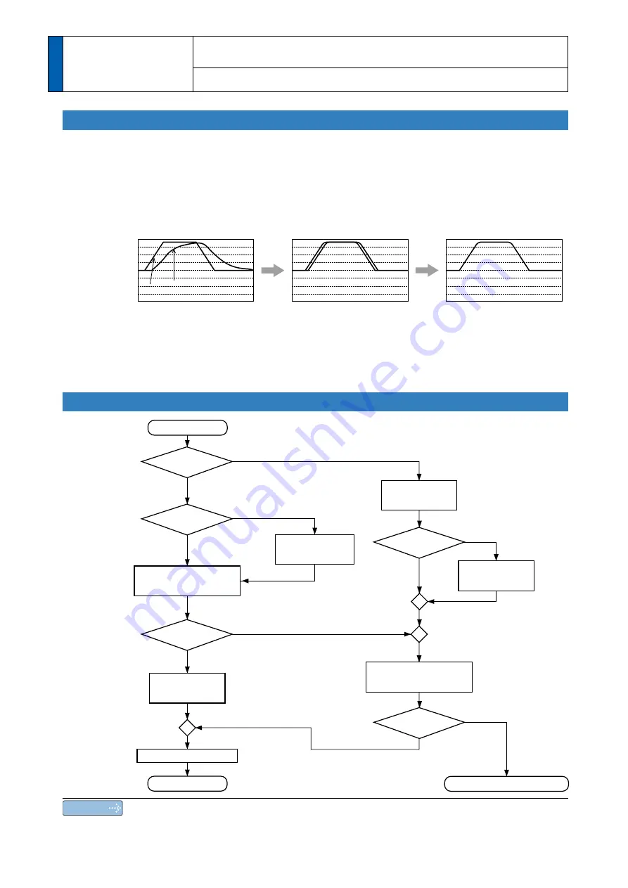
It is required for the servo driver to run the motor in least time delay and as faithful as
possible against the commands from the host controller. You can make a gain adjustment
so that you can run the motor as closely as possible to the commands and obtain the op
-
timum performance of the machine.
<e.g. : Ball screw>
Procedures
Position loop gain
: 20
Velocity loop gain
: 100
Time constant of
V-loop integration
: 50
Velocity loop feed forward : 0
Inertia ratio
: 100
Position loop gain
: 100
Velocity loop gain
: 50
Time constant of
V-loop integration
: 50
Velocity loop feed forward : 0
Inertia ratio
: 100
Position loop gain
: 100
Velocity loop gain
: 50
Time constant of
V-loop integration
: 50
Velocity loop feed forward : 500
Inertia ratio
: 100
+2000
-
2000
0
0.0
375
250
125
0.0
375
250
125
0.0
375
250
125
[r/min]
Command Speed
Motor actual speed
Gain setup : Low
Gain setup : High
Gain setup : High + feed forward setup
Start adjustment
Automatic
adjustment ?
Ready for
command
input ?
Action O.K.?
Yes
Yes
No
No
Yes
Yes
No
Action O.K.?
Yes
No
No
Real time
auto-gain tuning
(Default)
Release of
auto-adjusting
function
Release of
auto-adjusting
function
Manual gain tuning
Gain automatic
setup function
Finish adjustment
Writing to EEPROM
Consult to authorized dealer
(see P.5-4)
(see P.5-17)
Operation by using
the trial run function
(see P.5-24)
Use the
gain setup of auto-
adjustment ?
Note
For safety operation, first adjust the gain by referring to P.6-15 Setup protective function
before gain adjustment.
Summary of Contents for MADHT1105
Page 36: ...1 24 MEMO ...
Page 118: ...2 82 MEMO ...
Page 168: ...3 50 MEMO ...
Page 272: ...5 42 MEMO ...


