56
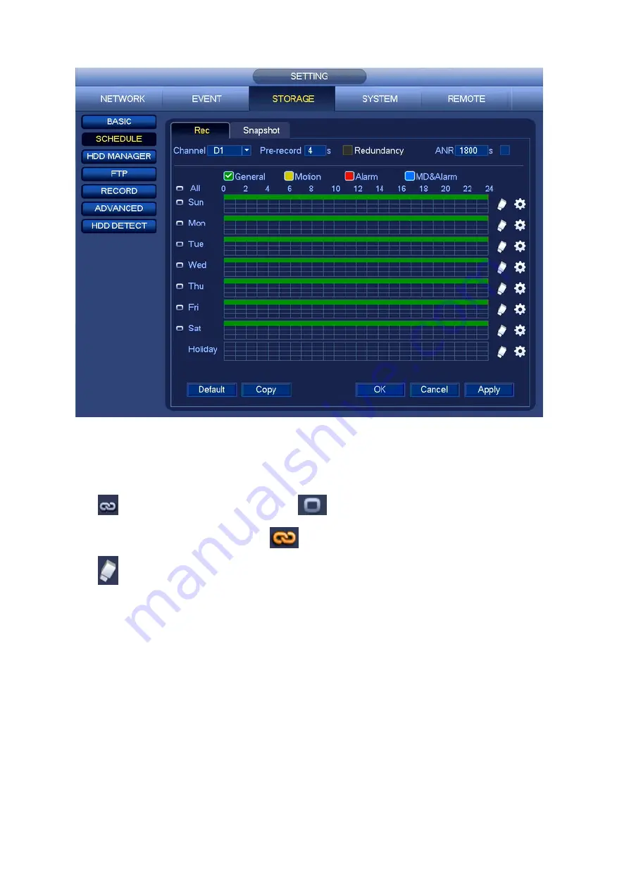
Figure 4-51
Channel: Please select the channel number first. You can select
“
all
”
if you want to set for the whole
channels.
: Sync connection icon. Select icon
of several dates, all checked items can be edited or
together. Now the icon is shown as
.
: Click it to delete a record type from one period.
Record Type: Please check the box to select corresponding record type. There are four types:
Regular/MD (Motion detect)/Alarm/MD&Alarm.
Week day: There are eight options: ranges from Saturday to Sunday and all.
Holiday: It is to set holiday setup. Please note you need to go to the General interface (Main
Menu->SETTING->SYSTEM->GENERAL) to add holiday first. Otherwise you cannot see this item.
Pre-record: System can pre-record the video before the event occurs into the file. The value ranges
from 1 to 30 seconds depending on the bit stream.
Redundancy: System supports redundancy backup function. It allows you backup recorded file in
two disks. You can highlight Redundancy button to activate this function. Please note, before enable
this function, please set at least one HDD as redundant. (Main menu->SETTING->STORAGE->HDD
MANAGER).
Please note this function is null if there is only one HDD.
ANR: It is to save video to the SD card of the network camera in case the network connection fails.
The value ranges from 0s
~
43200s. After the network connection resumed, the system can get the
video from the SD card and there is no risk of record loss.
Summary of Contents for K-NL404K/G
Page 1: ...Network Disk Recorder User s Manual Model No K NL404K G K NL408K G K NL416K G Version 1 0 1 ...
Page 25: ...19 3 4 Connection Sample Please refer to Figure 3 1 for connection sample Figure 3 1 ...
Page 69: ...63 Figure 4 61 Figure 4 62 ...
Page 90: ...84 Figure 4 78 Figure 4 79 ...
Page 91: ...85 Figure 4 80 Figure 4 81 ...
Page 99: ...93 Figure 4 87 Figure 4 88 ...
Page 100: ...94 Figure 4 89 Figure 4 90 ...
Page 101: ...95 Figure 4 91 Figure 4 92 ...
Page 104: ...98 Figure 4 94 Figure 4 95 ...
Page 112: ...106 Figure 4 104 Figure 4 105 ...
Page 121: ...115 Figure 4 115 ...
Page 127: ...121 Figure 4 120 Figure 4 121 ...
Page 132: ...126 Figure 4 125 Figure 4 126 ...
Page 139: ...133 Figure 4 133 Figure 4 134 ...
Page 141: ...135 Figure 4 136 ...
Page 143: ...137 ...
Page 146: ...140 Figure 4 140 Step 2 Click Add user button Enter Add user interface See Figure 2 141 ...
Page 151: ...145 Figure 4 144 1 ...
Page 157: ...151 ...
Page 158: ...152 Please input your username and password Figure 5 3 ...
Page 191: ...185 Figure 5 41 ...
Page 192: ...186 Figure 5 42 ...
Page 193: ...187 Figure 5 43 Figure 5 44 Figure 5 45 ...
Page 198: ...192 ...
Page 199: ...193 Figure 5 49 ...
Page 205: ...199 Figure 5 55 Figure 5 56 ...
Page 208: ...202 Figure 5 60 Figure 5 61 Figure 5 62 ...
Page 239: ...233 ...


