203
Please refer to the following sheet for detailed information.
Parameter Function
Channel
Please select a channel from the dropdown list.
Pre-record Please input pre-record time here. The value ranges from 0 to 30.
Redundancy Check the box here to enable redundancy function.
Please note this
function is null if there is only one HDD.
Snapshot
Check the box here to enable snapshot function.
Holiday
Check the box here to enable holiday function.
Setup
Click the Setup button, you can set record period. See Figure 5-61.
There are six periods in one day. If you do not check the date at the
bottom of the interface, current setup is for today only.
Please click Save button and then exit.
Copy
Copy function allows you to copy one channel setup to another. After
setting in channel, click Copy button, you can go to interface Figure
5-58. You can see current channel name is grey such as channel 1.
Now you can select the channel you want to paste such as channel
5/6/7. If you want to save current setup of channel 1 to all channels,
you can click the first box “ALL”. Click the Save button to save current
copy setup. Click the Save button in the Encode interface, the copy
function succeeded.
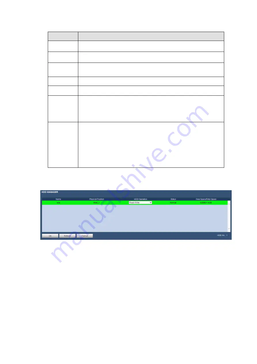
5.8.4.3 HDD Manager
The local interface is shown as in Figure 5-63. Here you can see HDD information. You can also operate
the read-only, read-write, redundancy (if there are more than on HDD) and format operation.
Figure 5-63
5.8.4.4 Record
The interface is shown as in Figure 5-64.
Summary of Contents for K-NL404K/G
Page 1: ...Network Disk Recorder User s Manual Model No K NL404K G K NL408K G K NL416K G Version 1 0 1 ...
Page 25: ...19 3 4 Connection Sample Please refer to Figure 3 1 for connection sample Figure 3 1 ...
Page 69: ...63 Figure 4 61 Figure 4 62 ...
Page 90: ...84 Figure 4 78 Figure 4 79 ...
Page 91: ...85 Figure 4 80 Figure 4 81 ...
Page 99: ...93 Figure 4 87 Figure 4 88 ...
Page 100: ...94 Figure 4 89 Figure 4 90 ...
Page 101: ...95 Figure 4 91 Figure 4 92 ...
Page 104: ...98 Figure 4 94 Figure 4 95 ...
Page 112: ...106 Figure 4 104 Figure 4 105 ...
Page 121: ...115 Figure 4 115 ...
Page 127: ...121 Figure 4 120 Figure 4 121 ...
Page 132: ...126 Figure 4 125 Figure 4 126 ...
Page 139: ...133 Figure 4 133 Figure 4 134 ...
Page 141: ...135 Figure 4 136 ...
Page 143: ...137 ...
Page 146: ...140 Figure 4 140 Step 2 Click Add user button Enter Add user interface See Figure 2 141 ...
Page 151: ...145 Figure 4 144 1 ...
Page 157: ...151 ...
Page 158: ...152 Please input your username and password Figure 5 3 ...
Page 191: ...185 Figure 5 41 ...
Page 192: ...186 Figure 5 42 ...
Page 193: ...187 Figure 5 43 Figure 5 44 Figure 5 45 ...
Page 198: ...192 ...
Page 199: ...193 Figure 5 49 ...
Page 205: ...199 Figure 5 55 Figure 5 56 ...
Page 208: ...202 Figure 5 60 Figure 5 61 Figure 5 62 ...
Page 239: ...233 ...


