1-11-6
1
U-200PZH2E8, U-250PZH2E8
WARNING
This air conditioner must be installed in accordance with national wiring regulations.
Cables connected to outdoor unit must be approved polychloroprene sheathed type 60245 IEC57 or H05RN-F/H07RN-F or heavier.
The units must be connected to the supply cables f
or fi
xed wiring b
y qualified technician.
Circuit breaker must be incorpor
ated in the fi
xed wiring in accordance with the national wiring regulations.
The circuit breaker must be approved, suitable for the voltage and current ratings of equipment and have a contact separation by 3mm in all
poles.
When the supply cable is damaged, it must be replaced by qualified technician.
Be sure to install a current leakage breaker, main switch and fuse to the main power supply, otherwise electric shocks may result.
Be sure to connect the unit to secure earth connection.
If the earthing work is not carried out properly, electric shocks may result.
the terminal connection section.
Wiring shall be connected securely by using specified cables and fix them securely so that external force of the cables may not transfer to
Imperf
ect connection and fixing leads to fir
e, etc.
Ensure to connect the electrical cable connections and clamp the wires securely to the terminal connections using cord clamps so that no undue force is
placed on the wires (power source cable, indoor/outdoor connection cables, earth lead wire).
Do not install a phase advance capacitor for power factor improvement. (It does not improve the power factor and will cause abnormal overheating.)
Do not bind the excess cables together and place them inside this unit.
Protect the electrical cable with the protective bushing provided so that the cables do no get damaged on the knock hole or etched portions. If there is space
between the electrical cables and the protective bushing occurs, seal it accordingly.
Tie the cables with the provided binding strap so that they do not touch the compressor and the tubes.
When setting up the cables, inside of unit install properly so that the front panel will not lift up. Make sure that front panel mount correctly.
Use a round type terminal with an insulation sleeve for connecting to the terminal block.
Use the appropriate screwdriver for tightening the terminal screws. Small sized screwdriver damages the head of the screw and cannot tighten it properly.
There is risk of damaging the screw if the terminal screw is over tightened. Tighten with the appropriate torque.
Screw diameter name
Tightening torque N•m{k
g
f•cm}
M4
1.57~1.96 {16~20}
M5
1.96~2.45 {20~25}
M6
4.00~4.50 {41~46}
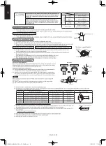
Direction to pull out wires
Earth lead wire set up
Front
direction
Sideways
direction
Back
direction
Seal wiring holes after wiring using
included protection bush. (other holes
are for connecting conduit tube)
The earth lead wire shall be longer than
other lead wires as sho
wn in the figure
for
electrical safety in case it slips out of the
cord from the anchorage.
Be sure to connect the wires correctly to terminal board with
connecting the crimp type ring terminal to the wires.
If connecting two separate wires to a single crimped terminal, place
the two crimped terminal wires together as shown in Fig. A.
(If the arrangement shown in Fig. B is used, poor contacts or contact
damage may result.)
Fig. A (OK)
Fig. B (not OK)
Wiring System Diagrams
Power supply (220-230-240V~)
Circuit breaker
Circuit breaker
Control cable
Wired remote
controller
Indoor unit
Outdoor unit
protective
earth
protective earth
Switch
Switch
Power supply (380-400-415V 3N~)
ACXF75-09810
Forced stop connection terminal block
Demand connection terminal block
Cord clamp
Cord
clamp
Cord clamp
Earth ter
minal fixing
for
(
: Shows the earth for the shielded cable)
Subsystem connection terminal block
Indoor/outdoor connection terminal block
Power supply terminal block
Earth lead wire
Earth terminal
Power line
Indoor/outdoor
connection
(shielded cable)
Thermal insulating
tubing materials
Indoor/outdoor, 2-wire mode format, option connection
(demand, forced stop and subsystem connections only)
Insulate the terminal
portion (earth included)
with insulation sleeves.
Carry out wiring so that
wires are not stretched.
fi
rmly with cord clamps.
Please tie the insulation tubing securely so that no
electrical lines do come into contact with the
compressor or exposed tubing.
Standard accessories: tying bands (4)
Shielded cable option control (when carrying out
demand, forced stop and subsystem connection
only).
This equipment complies with EN/IEC 61000-3-12 provided that the short-circuit power Ssc is
greater than or equals to *2 kVA at the interface point between the user’s supply and the public
system. It is the responsibility of the installer or user of the equipment to ensure; by consultation
with the distribution network operator if necessary that the equipment is connected only to supply
with a short-circuit power Ssc greater than or equals to *2 kVA.
Ssc : Short circuit power
: functional earthing
(for the shielded cable)
Model name
Power supply
Time delay fuse or
circuit capacity
*1
Control cable
*2
Ssc
U-200PZH2E8 380-400-415V 3N~
30 A
0.75 mm²
*3
U-250PZH2E8 380-400-415V 3N~
30 A
0.75 mm²
1850 kVA
*1 Use a shielded cable for the control cable. Overall extension less than 1000m.
*3 Intended for professional use. Permission from the power supplier is required when installing
the U-200PZH2E8 outdoor units that are connected to a 16 A distribution network.
SM830276-00_欧州向け R32シングル TD&SM.indb 6
2019/02/27 11:54:23
Summary of Contents for Elite Big PAC-i S-200PE3E5B
Page 12: ...MEMO Xi SM830276 00_ R32 TD SM indb 12 19 02 26 15 26 22...
Page 160: ...1 14 8 MEMO SM830276 00_ R32 TD SM indb 8 2019 02 27 11 55 39...
Page 176: ...MEMO 2 16 SM830276 00_ R32 TD SM indb 16 19 02 28 13 23 00...
Page 182: ...MEMO 3 6 SM830276 00_ R32 TD SM indb 6 19 02 26 10 39 17...
Page 238: ...MEMO 5 38 SM830276 00_ R32 TD SM indb 38 19 02 28 13 29 52...
Page 316: ...201903 SM830276 00_ R32 TD SM indb 1 19 02 15 8 52 12...


