2
2
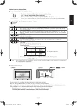
2-9
SW 1
SW 2
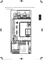
2-8-2. Setting the Outdoor unit system addresses
For basic wiring diagram (Set the system address: 1)
ON
1
2
Fig. 2-7
DIP switch
System address
System address rotary switch
(Set to “0” at time of shipment)
System address rotary switch
10s
20s
ON
OFF
Outdoor unit control PCB
System address
No.
System address
10s digit
(2P DIP switch)
System address
1s place
(Rotary switch)
0 Automatic address
(Setting at shipment = “0”)
Both OFF
ON
1
2
“0” setting
1 (If outdoor unit is No. 1)
Both OFF
ON
1
2
“1” setting
ON
OFF
ON
OFF
Outdoor main PCB
LED1
CHK pin
PUMPDOWN
RUN pin
MODE pin
*MODE pin: factory setting is cooling operation
mode.
LED2
SM830276-00_欧州向け R32シングル TD&SM.indb 9
19/02/28 13:22:58
Summary of Contents for Elite Big PAC-i S-200PE3E5B
Page 12: ...MEMO Xi SM830276 00_ R32 TD SM indb 12 19 02 26 15 26 22...
Page 160: ...1 14 8 MEMO SM830276 00_ R32 TD SM indb 8 2019 02 27 11 55 39...
Page 176: ...MEMO 2 16 SM830276 00_ R32 TD SM indb 16 19 02 28 13 23 00...
Page 182: ...MEMO 3 6 SM830276 00_ R32 TD SM indb 6 19 02 26 10 39 17...
Page 238: ...MEMO 5 38 SM830276 00_ R32 TD SM indb 38 19 02 28 13 29 52...
Page 316: ...201903 SM830276 00_ R32 TD SM indb 1 19 02 15 8 52 12...


