5
#5
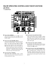
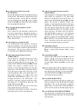
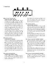
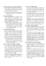
Option Switch [OP, ON/OFF]
Controls the option switch terminal on the Pan/tilt Head
AC Adapter (AW-PS300) to short circuit or open it. That
is, the option switch terminal is shorted when OP
ON/OFF Switch
#5
is in the ON position, or is opened
when it is in the OFF position. For details, refer to the
Operating Instructions for the Pan/tilt Head AC Adapter.
#6
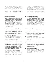
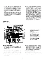
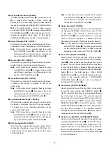
Zoom Lever [ZOOM, TELE/WIDE]
Controls the lens zoom. Zoom speed varies according
to the angle of the lever. The lens moves toward TELE
when the lever is moved toward TELE, or toward WIDE
when the lever is moved toward WIDE, provided that
ZOOM REVERSE Switch
%1
is in the NOR position.
When ZOOM REVERSE Switch
%1
is set to the REV
position, the lens moves in the opposite direction.
ZOOM/FOCUS EXCHANGE Switch
%2
may be used to
exchange its function with FOCUS Lever
#7
.
#7
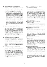
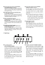
Focus Lever [FOCUS FAR/NEAR]
Used to adjust the lens focus at varying speed depend-
ing on the angle of the lever. The lens is focused far
when the lever is moved toward FAR, or near when the
lever is moved toward NEAR, provided that FOCUS
REVERSE Switch
%3
is in the NOR position. When
FOCUS REVERSE Switch
%3
is set to the REV position,
the lens focus operates in the opposite direction.
ZOOM/FOCUS EXCHANGE Switch
%2
may be used to
exchange its function with ZOOM Lever
#6
.
#8
Pan/tilt Lever [PAN/TILT, UP/DOWN/LEFT/RIGHT]
Controls the head’s pan/tilt operation at varying speed
depending on the angle of the lever. The pan/tilt head
turns up when the lever is moved toward UP, or down
when it is moved toward DOWN, provided that TILT
REVERSE Switch
%4
is in the NOR position. The
pan/tilt head moves in the opposite direction if the TILT
REVERSE Switch
%4
is in the REV position. The pan/tilt
head turns leftward when the lever is moved toward
LEFT, or rightward when it is moved toward RIGHT,
provided that PAN REVERSE Switch
%5
is in the NOR
position. The pan/tilt head moves in the opposite direc-
tion if the PAN REVERSE Switch
%5
is in the REV posi-
tion.
Note: TILT REVERSE Switch
%4
and PAN REVERSE
Switch
%5
may be used to reverse the operating
direction of the pan/tilt head, but be sure to set the
operating direction of the pan/tilt head with its
mounting direction selection switch during its instal-
lation depending on whether the pan/tilt head is
mounted on the floor or is suspended. Unless the
mounting direction selection switch on the pan/tilt
head is properly set, the pan/tilt head will pan or tilt
in the opposite direction and the pan/tilt head opera-
tion limiters will not be properly stored in the memo-
ry. For details on the setting of this switch, refer to
INSTALLATION OF PAN/TILT HEAD at page 18 or
the Operating Instructions for the Pan/tilt Head.
■
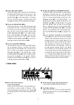
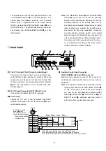
REAR PANEL
T A L L Y
H O T
D C 1 2 V I N
A U X C O N T R O L I N
V I D E O I N
O U T
G / L O U T
VIDEO OUT 1 VIDEO OUT 2
C O N T R O L
C O N T R O L O U T
P A N / T I L T
C A M E R A
T O C A M E R A P A N / T I L T H E A D
G / L I N
S - V I D E O O U T
#9
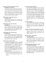
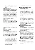
TALLY Input Terminal [TALLY]
(2-pin Terminal Board)
Connect it to the tally connector on a special effect gen-
erator (SEG) or a video switcher, for example. When
[HOT] terminal falls to ground level, TALLY Indicator
@2
and the tally indicator on the Pan/tilt Head (AW-PH300)
light red.
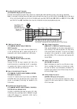
$0
12V DC Input Connector [DC 12V IN] (DC Jack)
Connect the AC Adapter AW-PS301 (optional).
$11
Cord Clamp (Clamper)
Clamps the DC cord of the AC Adapter AW-PS301
(optional) connected to DC 12V IN Connector
$0
to pre-
vent its disconnection.

