83
“INSTRUMENT PANEL”
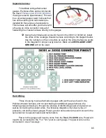
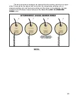
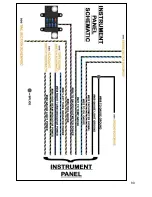
The instrument panel connections of the Painless harness will vary according to
the gauge cluster or aftermarket gauges you are using.
The wires for this connection will be grouped together with a section label
reading “INSTRUMENT PANEL”, these wires are:
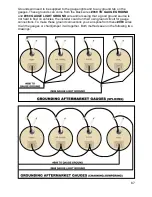
Black
: 16 gauge wire, printed
[INSTRUMENT PANEL] #969 TO GAUGE GROUND
,
this wire provides a ground source for the gauges. This wire is tied into the ground
circuit and can be seen in the
Ground Schematic
on page 14.
Black
: 16 gauge wire, printed
[INSTRUMENT PANEL] #969 GAUGE LIGHT GROUND
,
this wire provides a ground source to the backlighting of the gauges. This wire is tied
into the ground circuit and can be seen in the
Ground Schematic
on page 14.
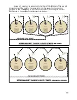
Black/White:
18 gauge wire, printed
[INSTRUMENT PANEL] #930 GAUGE LIGHT
POWER
, this wire will provide a power source for gauge back lighting. The black/white
#930
is tied to the other
#930
wire coming from the headlight switch that goes to the
radio backlight/dim. This wire will have power anytime the headlight switch is in the
Park/Tail Lights ON or Headlights ON position. This wire can also be seen in the
Headlight Switch
Schematic
on page 61.
Black/Tan:
18 gauge wire, printed
[TAIL SECTION] <<FUEL SENDER #939 FUEL
GAUGE>> [INSTRUMENT PANEL ]
, this wire is a ground signal from the fuel level
sending unit in the fuel tank. The resistance to ground will vary on this wire according to
the amount of fuel in the tank. This wire can also be seen in the
Tail Section Schematic
on pages 100 & 101.
Black/Pink:
18 gauge wires, both printed
[INSTRUMENT PANEL] #935 TO
GAUGE/VOLTMETER POWER
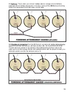
, this wire provides a switched ignition power source to
the cluster. This wire comes from the 10 amp GAUGES fuse on the fuse block. This
wire will have power anytime the key is in the ON/RUN position.
Black/Green:
18 gauge wire, printed
[ENGINE SECTION] TO TEMP SENDER #921
TO TEMP GAUGE [INSTRUMENT PANEL]
, this wire is a ground signal from the
engine coolant temperature sending unit. The sending unit will create resistance to
ground according to engine temperature. This resistance is transferred through this wire
to the gauge. This wire can also be seen in the
Ignition Switch Schematic
on page 79.
Black/White:
18 gauge wire, printed
[ENGINE SECTION] COIL(-) #923
TACHOMETER SIGNAL [INSTRUMENT PANEL]
, this wire is a ground signal from the
negative side of the ignition coil. This wire can also be seen in the coil connection
diagrams on page 34.
Black/Lt. Blue:
18 gauge wire, printed
[ENGINE SECTION A] TO OIL SENDER #922
TO OIL GAUGE [INSTRUMENT PANEL SECTION]
, this wire is a ground signal from
the oil pressure sending unit. The sending unit will create resistance to ground
according to oil pressure. This resistance is transferred through this wire to the gauge.

