39
START/CHARGE Section
The
Start/Charge Section
consists of five wires for connections to the alternator,
starter solenoid, and in line MIDI fuse (included with the kit). Locations of all of these
components will vary from vehicle to vehicle so no specific routing instructions can be
given.
Locate the bag kit provided with the Painless harness labeled “ALTERNATOR”.
This bag kit will contain hardware needed to make the appropriate connections to the
alternator as well as contain a covered inline fuse holder.
“Alternator”
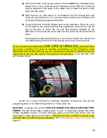
The alternator connections will vary depending on the alternator your vehicle
currently has installed. The alternator may also need to be removed in order to gain
access to the connection points.
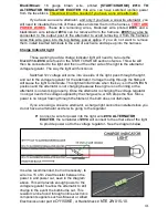
The one connection all alternators will have in common is the output post. This
will send amperage from the alternator to the battery. This connection will be made
using the large gauge red wire rolled in the kit , it is:
Red
: 6 gauge wire, with a label printed
#915 ALTERNATOR OUTPUT,
this wire will
provide power out of the alternator to the battery through the MAXI fuse. This wire will
have power at all times and comes from the large battery supply splice in the harness.
See
Charge/Battery Power Schematic
on page 53.
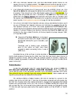
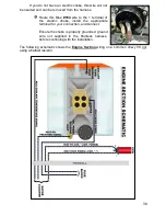
Locate the rubber alternator boot and
a large un-insulated ring terminal from
the
“ALTERNATOR” bag that has the
right size opening for your alternator
post. The piece of red heat shrink may
be used along with the boot or just by
itself over the terminal crimp if the
alternator boot is not desired.
A piece of wire loom is also provided
with this kit to cover the #915 charge wire after installation to help keep
with the all black theme of this harness. The charge wire is not a black
wire to help keep it from being confused with a negative/ground cable.
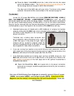
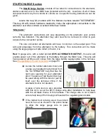
If the rubber boot is being used, the end will
need to be cut as shown in the photo below
to allow the large gauge wire to pass
through.

