

6
INTRODUCTION
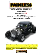
Thank you for your purchase of a Painless Performance product. These
instructions along with the Painless harness have been designed to allow you, the
installer, the cleanest and easiest install possible.
During the course of reading this manual you will notice wire colors with a slash,
as an example Black/White. This indicates a wire with a stripe. The first color is the
main color of the wire and the color after the slash is the stripe color. In the case of the
example, Black/White indicates a black wire with a white stripe.
Do not let the length of this instruction manual intimidate you. Much of the
information contained in this manual is helpful information about each wire, where the
wire comes from, where it goes, why a component needs it, etc. In many cases, there
are multiple schematics as well as alternate connection options for the same
wire/connection point due this being a universal harness. You will find that the actual
install portions of this manual are pretty straight forward and easy to follow.
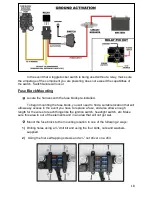
The install portions are noted with a round bullet note, as seen here.
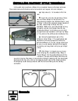
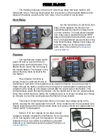
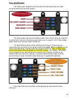
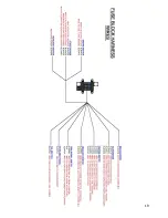
Individual components and sections are labeled with printed tags for easy
identification. As this harness is all black, conventional GM color code was followed
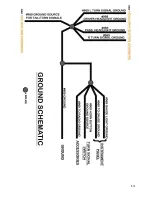
based on the stripe found on the wire. These colors, along with the schematic diagrams
found throughout this manual and the printed circuit numbers and description printed on
the wire, will help you identify the different circuits during installation and later on if
additions to the overall system are necessary.
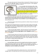
As you read through the installation manual prior to actual installation, use the
blank areas titled
NOTES
in each section and in the back of the manual to list
components you are connecting to on your vehicle, factory or manufacturer wires that
are coming from the component, then list their function/ power requirement. You can
then use the text in the manual and the wire index in the back of the manual to identify
the wire and circuit number in the Painless harness that will connect to that requirement.
For example, a dash mounted 60’s-70’s Ford ignition switch:


