


56
Mopar Starter Relay
Use the following instructions and diagrams if you are wiring in a Mopar starter
relay. Please be aware that if a ballast resistor is being used, you will need a relay with
a ballast terminal. These relays can be found using NAPA part # SR14 and can be used
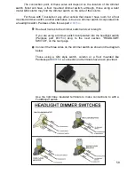
in installs that do or do not require a ballast resistor. Locate heat shrink and ring
terminals from the parts kit that best fit the posts/terminals found on the starter relay,
crimp and connect.
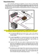
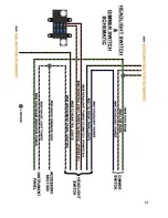
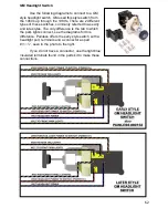
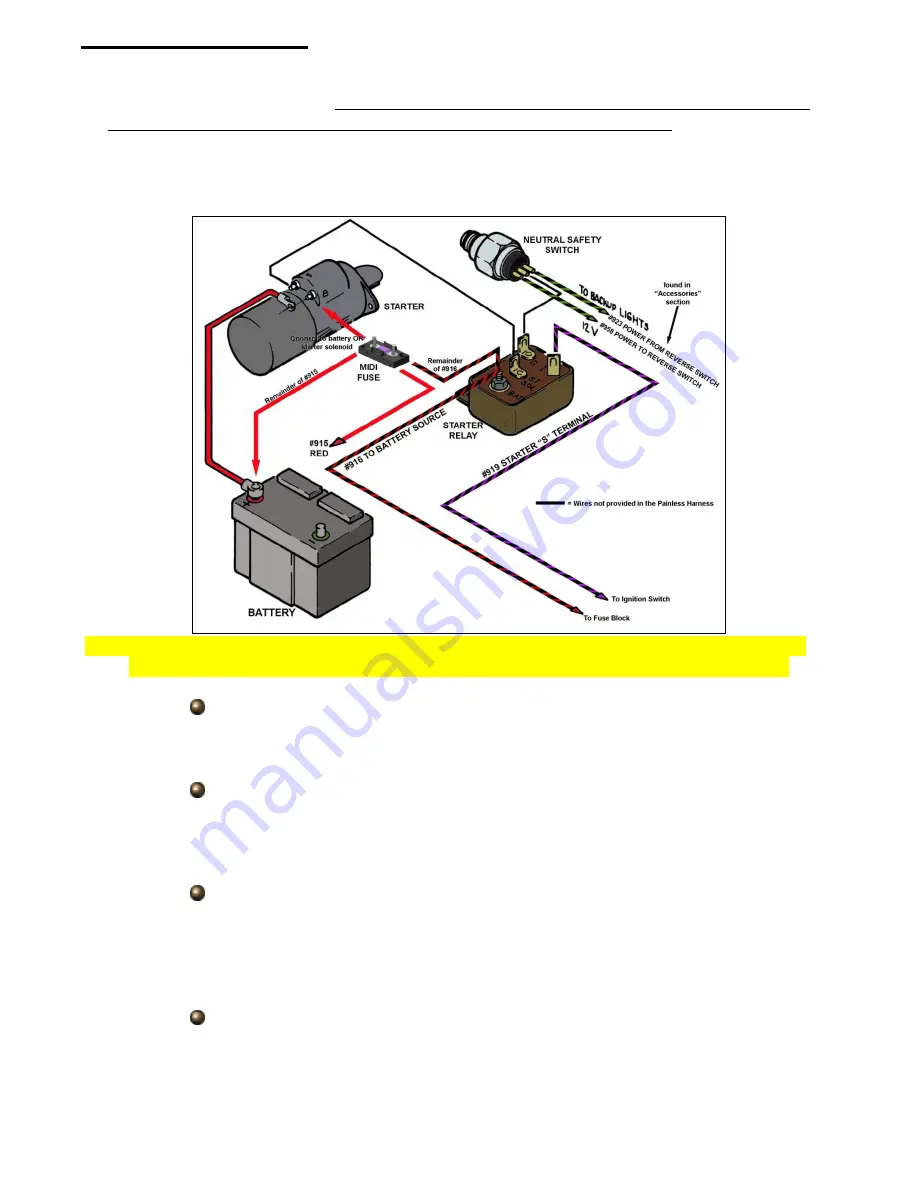
Use this diagram if you are not using a ballast resistor. If a ballast resistor is being used on
your installation, a diagram showing a “SR14” relay can be found on the next page.
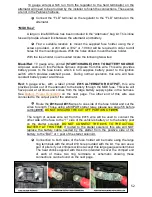
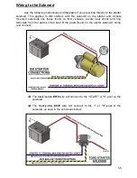
The black/purple
#919
wire will connect to the “I” post on the solenoid.
This will activate the relay when 12v is applied when the key is in the
“START” position.
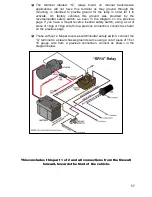
The black/yellow
#970
wire, if needed, will connect to the “BAL” terminal
found on a “SR14” relay, as seen in the diagram on the next page. The
“BAL” terminal, only found on the later style “SR14” relay, will have 12v
power ONLY when the relay has been activated.
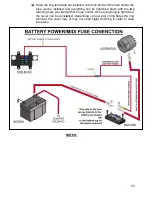
Connect the “BAT” post on the relay to a battery power source. This is
easily done by connecting this post to the output/harness side of the MIDI
fuse, inline on the
#916
wire as shown in the diagrams above and on the
following page. This post provides the power that is transferred through
the relay, to the starter.
The terminal on the relay marked “SOL” will need to have a wire that runs
from this terminal to the “S” post on the starter. This terminal on the relay
provides power to the starter solenoid. The Painless harness does not
have a wire dedicated for this connection, but a 12 or 14 gauge scrap wire
cut from another connection of this harness will work.


