
78
“BRAKE SWITCH”
The location of the brake switch will vary from vehicle to vehicle as this
connection depends on the style switch your vehicle uses.
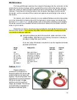
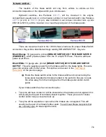
Hydraulic switches, like Painless
#80171
, will be mounted in the engine
compartment usually near or on the master cylinder. A mechanical switch, like Painless
#80172
(2 pin) or
#80176
(4 pin, also included in our torque converter lock up kits
#60109 & 60110), will be mounted on or near the pivot point of the brake pedal.
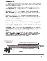
There are two wires found in the 10309 chassis harness for proper Brake Switch
connection, they will be identified will tags reading “BRAKE SWITCH”, they are:
Black/Orange
: 16 gauge wire, printed
[BRAKE SWITCH] #917 TO BRAKE SWITCH
(POWER B+)
, which provides power from the 15 amp STOP fuse. This wire will have
power at all times.
Black/White
: 16 gauge wire, printed
[BRAKE SWITCH] #918 TO BRAKE SWITCH
OUTPUT
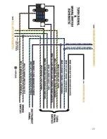
. This wire supplies power from the brake switch to the brake lights. This wire
goes into a splice with 2 other wires. This splice can be seen in the
Turn Signal
Schematic
on the previous page.
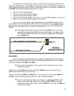
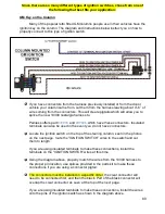
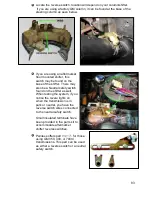
Route the brake switch wires to the brake switch and connect using the
loose piece insulated terminals provided in the parts kit. Be sure to route
the wires away from the moving parts of the brake pedal and/or clutch
pedal.
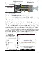
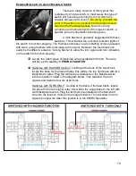
If your brake switch has four connection pins:
Two pins will have contact or will be closed when the brakes are not applied; this
will usually be the pair of terminals closest together. These pins are for cruise
control and/or torque converter lock up
Two pins will be separate or open when the brakes are not applied. This will
usually be the pair of terminals further apart. You will need these two posts that
are normally open for brake light function.


