20
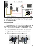
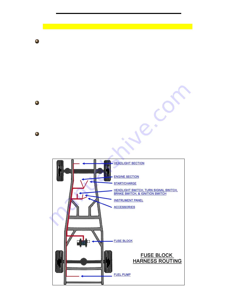
FUSE BLOCK HARNESS ROUTING
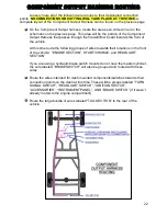
Loosely route all of the following wire groups to their designated connection
points.
NO CONNECTIONS OR CUTTING WILL TAKE PLACE AT THIS TIME.
A
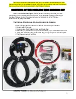
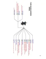
complete layout of the Fuse Block Harness can be found on the previous page.
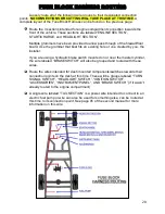
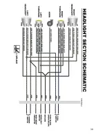
Route the 3 sections intended for engine compartment connection towards the
front of the vehicle. These sections are labeled “ENGINE SECTION”,
START/CHARGE, and HEADLIGHT SECTION”.
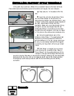
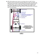
Multiple grommets have been provided to allow pass through of the firewall/floor
board. Use the grommet that best fits an existing hole or one created by you, the
installer.
If you are using a hydraulic brake switch mounted on or near the master cylinder,
the wire labeled “BRAKE SWITCH” will also be grouped and routed with these
wires.
Route the wires intended for dash mounted components/switches towards their
connection points on the dash at this time. These will be groups labeled “TURN
SIGNAL SWITCH”, “HEADLIGHT SWITCH”, “IGNITION SWITCH”,
“ACCESSORIES”, “INSTRUMENT PANEL”, AND “BRAKE SWITCH” (if it wasn’t
already routed to the engine compartment)
A single wire labeled “TAIL SECTION” is a power wire intended to connect to an
electric fuel pump or wire can also be used for something else, can be routed at
this time to its connection point. See page 95 of the second manual for more
information on this wire.


