©2016 PACE Inc., Vass, North Carolina,
All Rights Reserved
Page
18
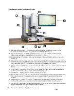
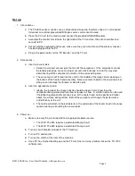
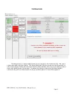
Example component removal – Note: If at any time you need to abort the process, click on the
red abort button.
1)
Turn on the TF machine and PC, and then run the TF software.
2)
Navigate to the Profiler Screen if not already there.
3)
Load a removal profile using the Load Profile button.
4)
Install the proper vacuum pick.
5)
Install the proper nozzle.
6)
Click “Start Process” and follow the onscreen instructions which will guide you through the
remainder of the procedure outlined in the following steps.
7)
Place the PCB between the arms on the board holder and tighten the retention screw.
8)
Position the board so the red laser point is roughly in the center of the component.
9)
Click on Start button.
10)
Allow PCB and component to cool before touching.
Developer Mode
Developer Mode has all the same features of Production Mode, with a few additions to allow the
creation and editing of installation and removal profiles. There are 2 recommended methods for developing a
profile. The first method involves an actual component installation, while the second uses a previously installed
package. Either method can be used to develop a reliable profile. However, there are some issues and
considerations to be aware of with each.
When developing a profile by doing a complete component installation, it is critical to make sure the
thermocouples remain in contact with the solder throughout the entire process. Unreliable data could be
generated should a thermocouple lose contact with the solder. If measuring temperature at the top of the
package, it is best to use a preinstalled component, as the thermocouple wire will typically cause the component
to not lay flat on the PCB which will cause problems with the install.
When using a previously installed package, the placement of the thermocouples is important. For best
results the sensors must be in contact with the existing solder joints. This task can be accomplished by drilling
through the bottom of the PCB into a solder joint and attaching the thermocouple, or by sliding the thermocouple
under the package. When sliding a thermocouple under a component, it is critical that the thermocouple be in
contact with the solder. Information from the thermocouples will assist in determining the proper time and
temperature parameters. It is imperative for the thermocouple sensor bead to be in contact with the solder
(preferred), the PCB and/or the component so that it is not floating in the open and measuring only the air
temperature.
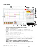
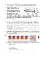
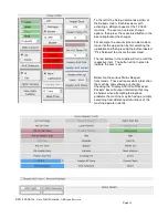
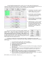
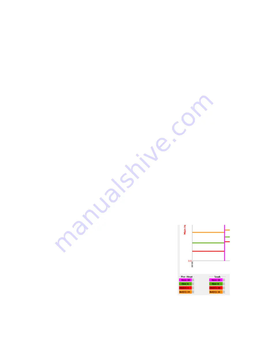
Adjusting the parameters for each phase or step of the profile is done
by moving the colored bars in each phase. More precise settings can be
input using the up/down arrows next to each entry at the bottom of the
temperature profile graph.
•
Magenta – Time in seconds
•
Green – Air flow in standard liters per minute
•
Red – Top heater set temperature
•
Orange – Bottom heater set temperature. (Note: As soon as a
temperature is put in the Preheat Zone for the bottom heater, the unit will
begin warming to that temperature.)
•
Purple – Auxiliary bottom heater temperature. (TF-2800 only.)

