©2016 PACE Inc., Vass, North Carolina,
All Rights Reserved
Page
4
Hardware Overview and Identification
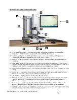
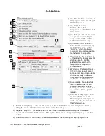
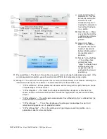
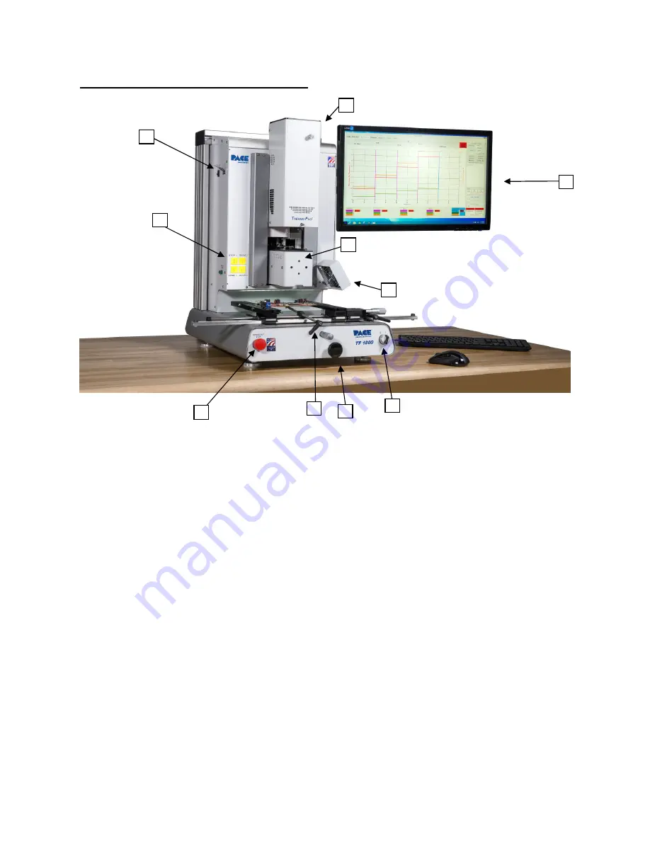
A) Pik-Vac switch and mount – The switch will activate the vacuum pump for 15 minutes so that
components can be handled manually with the included PV-65 Pik-Vac tool.
B) Thermocouple Inputs – Up to 4 K-type thermo-couples can be used to measure temperatures.
Temperature readings are displayed in real time via the TF software.
C) Emergency Stop – This button can be used to cut power to the machine immediately in case of an
emergency.
D) Board Holder with Board Support Wand – Fine adjustment of the board holder can be made in the X
and Y directions by using the micrometer knob on the front of the unit and right side of the holder itself.
The board holder also has a support bar to help prevent sag of large/heavy boards.
E) Bottom Heater Height Adjustment – Used to bring the bottom heater closer to the workpiece for faster
heating.
F) On/Off switch – Used to turn the machine on or off. Always turn the machine on before opening the
software, and allow the software to close before turning off the unit.
G) LCD Monitor – Displays software package from PC (not shown).
H) Reflow Head – Contains inductive-convection heater for fast and efficient top heating of components.
The entire head moves up and down via an electric stepper motor that is controlled through the
software.
I) Optics Housing – Contains the High-Def (1080p) Optical Alignment System (Camera, Prism and
lighting.) The optics housing extends and retracts automatically as needed during the process.
J) Cooling Fan – The component and PCB are cooled by the cooling fan, which is activated automatically
during the cool down zone or operated manually as needed.
A
B
C
D
E
F
G
H
J
I


