background image

©2016 PACE Inc., Vass, North Carolina, 

All Rights Reserved                                                                                                         


Page 

9  


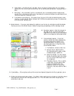
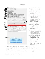
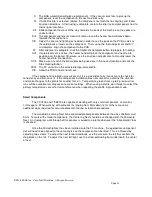
IV.  Align Holder – Checking this box will add a step in the process which guides the user through 

alignment of the vacuum pick and centering nest for working with components ranging between 1-
5mm. 

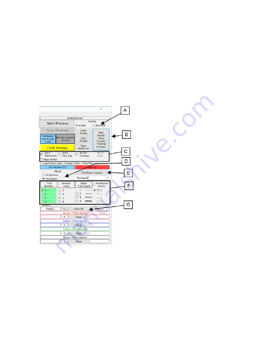
V.  Micro Chip – This automation routine is intended for use in installation profiles of components 

smaller than 1mm square, or whenever it would be more convenient to pick-up a component from 
the board instead of a component nest. 

VI.  Auto Removal (not pictured) – This option takes the place of the other automation options when 

creating a removal profile. When checked, the TF-1800 will automatically remove the component 
at the end of the heating cycle. 


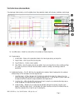
D)  Mode Indicator – The person developing the profile can use this box to switch back and forth between 

the two versions of the Profiler Screen, without having to log completely out of the developer mode. 


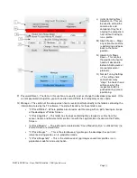
E)  Developer Logout – Click this to logout of 

developer mode.  Until the developer is 
logged back in profiles may only be loaded 
and run, no changes can be made to them. 


F)  Trial and Graph options – These four 

columns control information displayed on 
the profile graph while a profile is run 
during development, as well as what is 
seen by anyone later running the profile 
from Production Mode. 

I.  Trial Number – Selects active trial. 

II.  Sensors Used – Selects which 

thermocouple profile graphs will be 
recorded during a profile run. 

III.  Show Trial Graph – Can be used to 

display the profile graphs of multiple 
trial runs in the Profile Graph Chart 
for comparison. 

IV.  Production Sensor – This is used to 

select which thermocouple profile 
graph will be displayed on the 
production screen as the primary 
reference, once the profile has been 
saved. 


G)  Clear buttons – Pressing clear will reset the current and highest temperature for the respective sensor. 


H)  Profile instructions/specifications block – This block can be used to store text notes or instructions about 

the profile for future reference during production runs.  This information cannot be changed by the 
production mode user. 


Summary of Contents for TF-1800

Page 1: ...TF 1800 TF 2800 BGA Rework Station MANUAL NO 5050 0588 Revised 5 20 19 for software version 2 03 ...

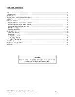
Page 2: ...reen Production Mode 1 The Profiler Screen Developer Mode 8 The Component Alignment Screen 10 The Setup Screen 12 The Debug Screen 14 Operation 16 General Overview 16 Procedure 17 Production Mode 17 Developer Mode 18 Small Components 20 Maintenance 21 Replacement Spare Parts 22 Warranty 23 WARNING Read the safety setup information sections in this manual before installing and using your new rework...

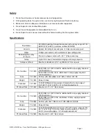
Page 3: ... Video Up to 240x zoom Quad Field imaging and image capture Component Nest Maximum 65x65mm 2 5 sq Minimum 1mm square 8007 0574 for 120V 50 60hz dedicated 20 amp supply required 1600 watt max Part number TF 1800 8007 0575 for 230v 50hz dedicated 10 amp supply required 1600 watt max Size TF 1800 737mm 29 H x 686mm 27 W x 737mm 29 D Weight TF 1800 45kg 100lbs Preheater TF 1800 1000 Watt Medium Long w...

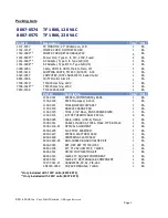
Page 4: ... EA Part Id Description Qty UM 1001 0001 STENCIL COMPONENTS LEADS 1 EA 1100 0100 PACE Mousepad 9 2014 1 EA 1100 0231 TOOL NOZZLE CHIP ASSY 1 EA 1100 0303 NOZZLE CHANGE PAD 1 EA 1132 0070 TOOL 3 32 BALL_END SCREWDRIVER 1 EA 1340 0174 K TYPE THERMOCOUPLE 40 GA 4 EA 3008 0295 Cable USB A USB B Male 6 1 EA 3008 0931 CABLE 1M USB3 0 TYPE A MALE TYPE B MALE 1 EA 4018 0100 P1 OPTICAL ALIGNMENT 1 EA 6000 ...

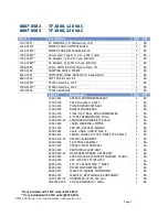
Page 5: ...4 1 EA 1100 0231 TOOL NOZZLE CHIP ASSY 1 EA 1100 0303 NOZZLE CHANGE PAD 1 EA 1132 0070 TOOL 3 32 BALL_END SCREWDRIVER 1 EA 1340 0174 K TYPE THERMOCOUPLE 40 GA 4 EA 1348 0700 01 LEG BOARD HOLDER KIT 5 25LG 1 EA 1351 0902 LABEL WARNING LIFTING 1 EA 1405 1047 SCR SKT 8 32X2 25 SSNAHS 4 EA 3008 0295 Cable USB A USB B Male 6 1 EA 3008 0931 CABLE 1M USB3 0 TYPE A MALE TYPE B MALE 1 EA 4018 0100 P1 OPTIC...

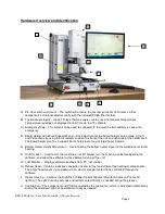
Page 6: ...as a support bar to help prevent sag of large heavy boards E Bottom Heater Height Adjustment Used to bring the bottom heater closer to the workpiece for faster heating F On Off switch Used to turn the machine on or off Always turn the machine on before opening the software and allow the software to close before turning off the unit G LCD Monitor Displays software package from PC not shown H Reflow...

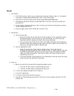
Page 7: ...aft in the middle of the large circular opening on the bottom of the heater head assembly Never use tools to tighten the vacuum pick as doing so can damage the threads or bend the pick b Insert an appropriate nozzle i Ideally the inside of the chosen nozzle should be about 3 mm larger than the component being worked with to allow for proper air flow A smaller nozzle can be used if neighboring comp...

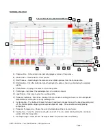
Page 8: ...emoval G Load Profile Click here to select an existing profile H Preheater Indicators Reference showing if the main and or auxiliary pre heater is at an acceptable temperature for starting the currently loaded profile I Cycle Heating This button will move the heater head down into position over the board assembly and run the thermal profile skipping all set up and alignment steps For use when manu...

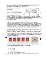
Page 9: ... Selecting two points on the same temperature curve will display the temperature over time or slope for that portion of the curve When Stairs Slope is checked selecting a point outside of an existing slope measurement will create a new measurement from the nearest end of the existing slope When Stairs Slope is not engaged selecting a point outside of an existing slope will lengthen the slope measu...

Page 10: ...sed during automatic operations C Automation Options The TF 1800 has the capability to remember heater head position to automate different steps in the installation or removal processes I Auto Placement When checked the TF 1800 will automatically place the component using distance settings input during the first profile development run If unchecked the heater head and component will have to be man...

Page 11: ...this to logout of developer mode Until the developer is logged back in profiles may only be loaded and run no changes can be made to them F Trial and Graph options These four columns control information displayed on the profile graph while a profile is run during development as well as what is seen by anyone later running the profile from Production Mode I Trial Number Selects active trial II Sens...

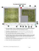
Page 12: ...this button will abort the operation and return to the previous screen while also returning the heater head and camera arm to their home positions D Quad Field Imaging These four viewports or quadrants allow portions of the Main Camera Image to be viewed in more detail when fine tuning alignment without the need for adjusting the Main Camera Image Use this feature by left clicking a point in the M...

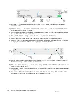
Page 13: ...igital magnification of the Quad Field Imaging L Focal Distance Depending on the sizes and distances of components and the board from the camera changing the focal distance of the camera may help when aligning the BGA M Dzoom Slider Used to zoom the Main Camera Image up to 9x The slider bars below and beside the Main Camera Image can be used to reposition the view N Sharpness Slider Adjusting this...

Page 14: ...g this box will prevent anyone from beginning a profile until the auxiliary preheaters have reached the temperature setting for the Preheat Zone G Auto Activate Preheater while idle Checking this box will allow the preheater to begin heating as soon as the machine is turned on before a profile is loaded H Allow Micro Chip Option This controls whether or not the Micro Chip automation process will b...

Page 15: ...d is forgotten you will need to contact PACE for a temporary access code Q Manage This section of the setup screen hosts several shortcuts directly to the folders containing the information stored by the TF software The default locations for these folders are C Pace Profiles Where profiles are stored as dat file along with an pdf showing an image of the developer s Profiler Screen C Pace LogFiles ...

Page 16: ...own into three sections The Setup Commands on the left will make the machine perform an action Status Request Commands will read off what the software believes to be the current setting position or status of the different parts of the machine The bottom area contains read outs for the Status Request commands along with a command selector to change available options for future BGA equipment ...

Page 17: ...st selecting the up bubble and then pressing the button labeled Pick Solenoid to activate the command The red buttons in the middle will turn on off the respective item The button will turn green to indicate the item is on Below are the various Status Request Commands These will query what information the machine and software are sharing Checking the Display ASCII Sent Received Packets box will ou...

Page 18: ...ds with large ground planes or other heat sinking materials and components will benefit from a longer soak period to ensure uniform temperatures Ramp Phase The ramp phase is where important things in the solder process start to happen The temperature should begin climbing in order to activate the flux Reflow Phase This is where everything comes together and the solder reaches liquidus The lowest s...

Page 19: ...r point is in the center of the placement site and tighten the board holder retention screw 8 Apply flux to the board if needed and attach any thermocouples desired for additional process monitoring Adjust the Board Support Wand as needed 9 Place the component in the mounting plate on top of the camera housing The component needs to have the same orientation as the nozzle Click okay 10 The BGA wor...

Page 20: ... process Unreliable data could be generated should a thermocouple lose contact with the solder If measuring temperature at the top of the package it is best to use a preinstalled component as the thermocouple wire will typically cause the component to not lay flat on the PCB which will cause problems with the install When using a previously installed package the placement of the thermocouples is i...

Page 21: ... process The included default profiles do not have any distances stored When altering any other pre existing profile to work with different components after loading the profile you must clear the distance settings with the New Profile button or the heater head could crash Following is a sample outline of steps needed to develop an installation profile by doing a new component installation The proc...

Page 22: ...re profile XIX Allow the PCB to cool and remove If the component installation was successful it is a good idea to try it once more to check for consistency and then save it If the component installation was not successful examine the situation and make changes to the profile for another trial run Temperature graphs from up to 3 previous trial runs will be available for comparison to current settin...

Page 23: ...OVG220 grease Mobil Vactra No 4 to rails Depending on the service conditions the rails should be lubricated as a preventative measure at least annually Vacuum pick bearings should be checked if pick does not fully descend to bottom position Must remove theta adjust knob and 4 screws to remove heater head cover Carefully clean off dust or debris from exposed parts of the vacuum tube with an anti du...

Page 24: ...uum 6020 0157 P1 TF Sensor PCB 1263 0036 P1 Proportional Valve 3008 0295 P1 USB A USB B Cable 1161 0008 P1 5x20mm Fuse Holder 1259 0135 P1 Vacuum Panel Mount Fitting 1334 0021 P1 Low Pressure Pump 6000 0239 P1 Laser Pointer 6000 0313 P1 Nitrogen Solenoid 7027 0001 P1 PV 65 Pik Vac Vacuum Wand 1121 0927 P1 Micro Vacuum Pik 20 gauge 1340 0174 P1 K type Thermocouples package of 2 6016 0033 Hex Key Se...

Page 25: ... user in the field at the user s expense and risk User will be responsible for all costs of shipping equipment to PACE or other warranty location for warranty service EXCEPT FOR THE REMEDY ABOVE DESCRIBED UNLESS OTHERWISE REQUIRED BY APPLICABLE LAW PACE WILL HAVE NO OTHER OBLIGATION WITH REGARD TO ANY BREACH OF WARRANTY OR OTHER CLAIM WITH RESPECT TO THE EQUIPMENT OR LIABILITY FOR ANY DIRECT INDIR...

Reviews: