


7
2. Mount the Dual Function Lever on the Screw Insert.
3. Secure the Lever Fixation Screw with a medium strength threadlocker.
4. Use the Guide Clips to determine where the Cable Guide will run.
5. Fix the Cable Guide in the Guide Clips.
6. Guide the Nylon Cord through the Cable Guide.
7. Set the Dual Function Lever in the lower position.
8. Snap the Release Lever
(Fig. 7: A)
into the device.
9. Fix the Nylon Cord to the Release Lever on the device.
Caution:
If the device is being used with the locking function, neither the
Release Lever
(Fig. 7: A)
nor the Nylon Cord may be impeded by the
cosmesis and they must be able to move freely.
Warning:
If readjustment work is required, secure the Nylon Cord so that
it cannot catch in grinding tools.
Note:
If the patient only wants to use the Dual Function Lever for
releasing the knee joint in certain situations (e. g., sitting down), the
enclosed M4 Allen Screws can be screwed into the slots in the Dual
Function Lever. This stops the lever from slipping up beyond the taper
and thus permanently inactivating the Release Lever
(Fig. 7: A)
.
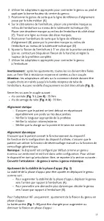
ALIGNMENT INSTRUCTIONS
Bench Alignment
(Fig. 2)
Alignment Goal
Alignment reference line (B) should:
– pass through midpoint of socket at the ischial tuberosity level (D)
– pass through midtube (A)
– fall at the 1/3 mark on the inside of the foot cover.
Note:
Prioritize knee alignment over foot alignment if there is
a mismatch.
Alignment Instructions
1. Position the foot so that the alignment reference line (B) falls at the
1/3 mark on the inside of the foot cover (with the foot cover and shoe
on). Consider the external rotation of the foot.
2. Use the applicable adapters to connect the knee to the foot and
establish the correct knee center height.
3. Position the knee so that the alignment reference line passes through
midtube (A)
4. On the lateral side of the socket, make a first mark at the midpoint of
the socket at the ischial tuberosity level (D). Make a second mark at the
midpoint of the socket distally (E). Draw a line through both marks.
5. Position the socket so the alignment reference line (B) goes through
first mark at the midpoint of the socket at the ischial tuberosity level
(D).
6. Adjust the socket flexion to 5° in addition to the existing position
7. (i. e., hip flexion contracture) and set the height of the full prosthesis.
8. Use the applicable adapters to connect the knee to the socket.
Warning:
After adjustments, all screws must be secured with a medium
strength threadlocker and tightened with the correct torque.
Caution:
Adapters used on the distal connection must be cut straight and
inserted down to the end stop of the device's tube receiver. No spacer
should be used
(Fig. 3)
.
Summary of Contents for OFM1
Page 1: ...Instructions for Use BALANCE KNEE OFM1...
Page 3: ...3 35Nm A B E F L M K J I G C D H B D C E A 5 A 1 2 3 4...
Page 4: ...4 A B A B A D C 5 6 7...
Page 57: ...57 1 36 mm B 3 IKF 136...
Page 58: ...58 36 mm 3 3 1 3 10 Nm 1 E E 1 1 I IA 2 3 35 Nm IKF A P...
Page 59: ...59 1 2 3 4 5 6 7 7 A 8 1 2 3 4 5 6 7 8 7 A 9 7 A Allen M4 7 A 2 B A 1 3 1 1 3...
Page 60: ...60 2 3 4 E 5 B 6 5 7 3 1 35 Nm 4 16 Nm 5 A B IKF 1 H...
Page 61: ...61 35 Nm 6 A 7 C 7 A B A B 5 Nm B B 5 Nm B A B A...
Page 62: ...62 B A D A D D 10 C 40 C 6 ssur...
Page 63: ...63 ISO 10328 3 5 ISO 10328 P6 136 kg...
Page 103: ...103 1 A 36 B C IKF D 136...
Page 104: ...104 36 1 B 10 1 E E F 1 1 L M I J K 2 3 35 IKF A P G...
Page 105: ...105 1 2 3 4 5 6 7 7 A 8 1 2 3 4 5 6 7 8 7 A 9 7 A M4 7 A 2 B D A 1 3 1 B 1 3...
Page 106: ...106 2 3 A 4 D E 5 B D 6 5 7 3 1 I J K 35 4 16 5 A B...
Page 107: ...107 IKF 1 H 35 6 A 7 C 7 A B A B 5 B B 5...
Page 108: ...108 B A B A B A D A D D 10 C 40 C 6...
Page 109: ...109 ssur ISO 10328 3 5 ISO 10328 P6 136 kg...
Page 110: ...110 4 4 1 A 3 36 mm B C IKF D 136 kg 1 3 36 mm 3 1 B 3 10 Nm...
Page 111: ...111 1 1 E E F Plastilin 1 1 L M I J K 2 3 35 Nm IKF A P G 1 2 3 4 5 6 7 7 A 8 1 2 3 4 5...
Page 113: ...113 Locking Knee 5 A B IKF 1 H 35 Nm 6 A 7 C...
Page 114: ...114 7 A B A B 5 Nm B B 5 Nm 2 B A B A B A D A D D 10 C 40 C 6...
Page 115: ...115 ssur 300 ISO 10328 3 5 ISO 10328 P6 136 kg...
Page 116: ...116 1 A 36 mm B 3 C IKF D 136 kg 36 mm B 3 3 1 B 10 Nm...
Page 117: ...117 1 E E F Plastilin 1 1 L M I J K 2 3 35 Nm IKF G A P 1 2 3 4 5 6 7 7 A 8 1 2 3 4 5...
Page 119: ...119 5 A B IKF 1 H 35 Nm 6 A 7 C...
Page 120: ...120 7 A B A 5 Nm B B B 5 Nm B A B A B A D A D D 10 C 40 C 6...
Page 121: ...121 ssur ISO 10328 300 3 5 ISO 10328 P6 136 kg...
Page 122: ...122 4 4 1 A 3 36mm B C IKF D 136kg...
Page 123: ...123 3 36mm 3 1 B 3 10Nm 1 E E F Plastilin 1 1 L M I J K 2 3 35Nm IKF A P G...
Page 124: ...124 1 2 3 4 5 6 7 7 A 8 1 2 3 4 5 6 7 8 7 A 9 7 A M4 7 A 2 B D A 1 3 1 B 1 3 2...
Page 125: ...125 3 A 4 D E 5 B D 6 5 7 3 1 I J K 35Nm 4 A 16Nm 5 A B IKF 1 H...
Page 126: ...126 35Nm 6 A 7 C 7 A B A B 5Nm B B 5Nm B A B A B A D A D...
Page 127: ...127 D 10 C 40 C 6 ssur...
Page 128: ...128 ISO 10328 300 3 5 ISO 10328 P6 136 kg...
Page 129: ...129...