


SECTION 5 - HYDRAULICS
5-4
– JLG Lift –
3120895
8.
Inspect seal and o-ring grooves in piston for burrs
and sharp edges. Dress applicable surfaces as nec-
essary.
9.
Inspect cylinder head inside diameter for scoring or
other damage and for ovality and tapering. Replace
as necessary.
10.
Inspect threaded portion of head for damage. Dress
threads as necessary.
11.
Inspect seal and o-ring grooves in head for burrs
and sharp edges. Dress applicable surfaces as nec-
essary.
12.
Inspect cylinder head outside diameter for scoring
or other damage and ovality and tapering. Replace
as necessary.
13.
If applicable, inspect rod and barrel bearings for
signs of correct excessive wear or damage. Replace
as necessary.
a.
Thoroughly clean hole, (steel bushing) of burrs,
dirt etc. to facilitate bearing installation.
b.
Inspect steel bushing for wear or other damage.
If steel bushing is worn or damaged, rod/barrel
must be replaced.
c.
Lubricate inside of the steel bushing with WD 40
prior to bearing installation.
d.
Using an arbor of the correct size, carefully
press the bearing into steel bushing.
NOTE:
Install pin into the composite bearing dry. Lubrication
is not required with nickel plated pins and bearings.
14.
Inspect travel limiting collar or spacer for burrs and
sharp edges. If necessary, dress inside diameter
surface with Scotch Brite or equivalent.
15.
If applicable, inspect port block fittings and holding
valve. Replace as necessary.
16.
Inspect the oil ports for blockage or the presence of
dirt or other foreign material. Repair as necessary.
17.
If applicable, inspect piston rings for cracks or other
damage. Replace as necessary.
Assembly
NOTE:
Prior to cylinder assembly, ensure that the proper
cylinder seal kit is used. See your JLG Parts Manual.
Apply a light film of hydraulic oil to all components
prior to assembly.
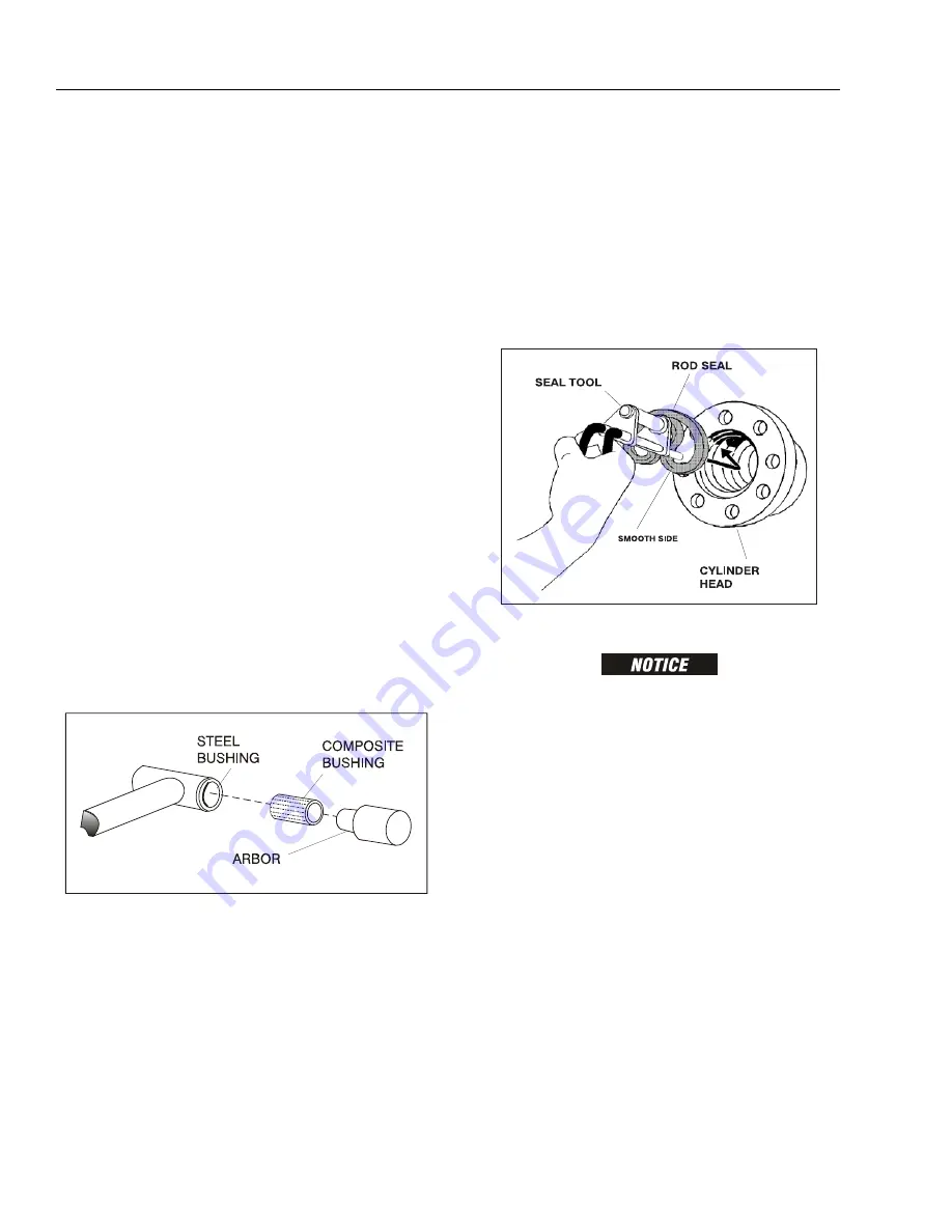
1.
A special tool is used to install a new rod seal into
the applicable cylinder head gland groove.
WHEN INSTALLING “POLY-PAK” PISTON SEALS, ENSURE SEALS
ARE INSTALLED PROPERLY. REFER TO WIPER SEAL INSTALLA-
TION FOR CORRECT SEAL ORIENTATION. IMPROPER SEAL
INSTALLATION COULD RESULT IN CYLINDER LEAKAGE AND
IMPROPER CYLINDER OPERATION.
2.
Use a soft mallet to tap a new wiper seal into the
applicable cylinder head gland groove. Install a new
wear ring into the applicable cylinder head gland
groove.
Figure 5-6. Composite Bearing Installation
Figure 5-7. Rod Seal Installation
Summary of Contents for JLG 400S
Page 1: ...Service and Maintenance Manual Models 400S 460SJ P N 3120895 December 6 2012...
Page 2: ......
Page 20: ...xvi JLG Lift 3120895 LIST OF TABLES TABLE NO TITLE PAGE NO This page left blank intentionally...
Page 52: ...SECTION 2 GENERAL 2 14 JLG Lift 3120895 NOTES...
Page 100: ...SECTION 3 CHASSIS TURNTABLE 3 48 JLG Lift 3120895 Figure 3 35 Swing Drive Installation...
Page 101: ...SECTION 3 CHASSIS TURNTABLE 3120895 JLG Lift 3 49 Figure 3 36 Swing Motor...
Page 105: ...SECTION 3 CHASSIS TURNTABLE 3120895 JLG Lift 3 53 Figure 3 38 Swing Brake S N 64802 to Present...
Page 107: ...SECTION 3 CHASSIS TURNTABLE 3120895 JLG Lift 3 55 Figure 3 39 Swing Torque Hub...
Page 124: ...SECTION 3 CHASSIS TURNTABLE 3 72 JLG Lift 3120895 Figure 3 44 EFI Component Location...
Page 136: ...SECTION 3 CHASSIS TURNTABLE 3 84 JLG Lift 3120895 Figure 3 49 Valve Location Chassis...
Page 137: ...SECTION 3 CHASSIS TURNTABLE 3120895 JLG Lift 3 85 Figure 3 50 Hyd Tank Installation...
Page 143: ...SECTION 3 CHASSIS TURNTABLE 3120895 JLG Lift 3 91 This page left blank intentionally...
Page 155: ...SECTION 3 CHASSIS TURNTABLE 3120895 JLG Lift 3 103 Figure 3 60 EMR2 Fault Codes Sheet 1 of 5...
Page 156: ...SECTION 3 CHASSIS TURNTABLE 3 104 JLG Lift 3120895 Figure 3 61 EMR2 Fault Codes Sheet 2 of 5...
Page 157: ...SECTION 3 CHASSIS TURNTABLE 3120895 JLG Lift 3 105 Figure 3 62 EMR2 Fault Codes Sheet 3 of 5...
Page 158: ...SECTION 3 CHASSIS TURNTABLE 3 106 JLG Lift 3120895 Figure 3 63 EMR2 Fault Codes Sheet 4 of 5...
Page 159: ...SECTION 3 CHASSIS TURNTABLE 3120895 JLG Lift 3 107 Figure 3 64 EMR2 Fault Codes Sheet 5 of 5...
Page 208: ...SECTION 3 CHASSIS TURNTABLE 3 156 JLG Lift 3120895...
Page 210: ...SECTION 3 CHASSIS TURNTABLE 3 158 JLG Lift 3120895...
Page 213: ...SECTION 3 CHASSIS TURNTABLE 3120895 JLG Lift 3 161...
Page 223: ...SECTION 3 CHASSIS TURNTABLE 3120895 JLG Lift 3 171 Sensor Transducer Type...
Page 227: ...SECTION 3 CHASSIS TURNTABLE 3120895 JLG Lift 3 175 Sensor Transducer Type...
Page 229: ...SECTION 3 CHASSIS TURNTABLE 3120895 JLG Lift 3 177...
Page 231: ...SECTION 3 CHASSIS TURNTABLE 3120895 JLG Lift 3 179...
Page 233: ...SECTION 3 CHASSIS TURNTABLE 3120895 JLG Lift 3 181...
Page 235: ...SECTION 3 CHASSIS TURNTABLE 3120895 JLG Lift 3 183...
Page 237: ...SECTION 3 CHASSIS TURNTABLE 3120895 JLG Lift 3 185...
Page 255: ...SECTION 3 CHASSIS TURNTABLE 3120895 JLG Lift 3 203...
Page 259: ...SECTION 3 CHASSIS TURNTABLE 3120895 JLG Lift 3 207...
Page 264: ...SECTION 3 CHASSIS TURNTABLE 3 212 JLG Lift 3120895 NOTES...
Page 288: ...SECTION 4 BOOM PLATFORM 4 24 JLG Lift 3120895 Figure 4 12 Rotator Counterbalance Valve...
Page 303: ...SECTION 5 HYDRAULICS 3120895 JLG Lift 5 15 Figure 5 22 Main Valve...
Page 313: ...SECTION 5 HYDRAULICS 3120895 JLG Lift 5 25 Figure 5 25 Variable Displacement Hydraulic Pump...
Page 402: ...SECTION 6 JLG CONTROL SYSTEM S N 61718 TO PRESENT 6 86 JLG Lift 3120895 NOTES...
Page 460: ...SECTION 7 BASIC ELECTRICAL INFORMATION SCHEMATICS 7 58 JLG Lift 3120895 NOTES...
Page 461: ......


