background image

SECTION 3 - CHASSIS & TURNTABLE

3-128

– JLG Lift –

3120895

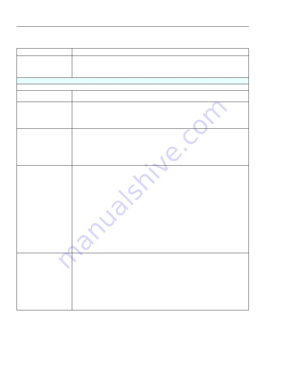
Exhaust System Checks

 Check the exhaust system for a possible restriction:                                    

     - Inspect the exhaust system for damaged or collapsed pipes
     - Inspect the muffler for signs of heat distress or for possible internal failure.

 Check for possible plugged catalytic converter. Refer to Restricted Exhaust System Diagnosis

Hard Start

DEFINITION: The engine cranks OK, but does not start for a long time. The engine does eventually run, or may start but immediately dies.

Preliminary Checks

 Refer to Important Preliminary Checks.
 Make sure the vehicle's operator is using the correct starting procedure.

Sensor Checks

Check the Engine Coolant Temperature sensor with the scan tool. Compare the engine coolant temperature with the 

ambient air temperature on a cold engine. IF the coolant temperature reading is more than 5 degrees greater or less than 
the ambient air temperature on a cold engine, check for high resistance in the coolant sensor circuit. Refer to DTC 111

 Check the Crankshaft Position (CKP) sensor.
Check the Throttle position (TPS) sensor.

Fuel System Checks

 Important: A closed LPG manual fuel shut off valve will create an extended crank OR no start condition.

 Verify the excess flow valve in the LPG manual shut-off valve is not tripped.
 Check mixer module assembly for proper installation and leakage.
 Verify proper operation of the low pressure lock-off solenoids.
 Verify proper operation of the EPR
 Check for air intake system leakage between the mixer and the throttle body.
 Check the fuel system pressures. Refer to the Fuel System Diagnosis. 

Ignition System Checks

 Note: LPG being a gaseous fuel requires higher secondary ignition system voltages for the equivalent gasoline operat-
ing conditions.

 Check for the proper ignition voltage output with J 26792 or the equivalent.
 Verify that the spark plugs are correct for use with LPG (R42LTS)
 Check the spark plugs for the following conditions:

     - Wet plugs
     - Cracks
     - Wear
     - Improper gap
     - Burned electrodes
     - Heavy deposits

 Check for bare or shorted ignition wires.
 Check for moisture in the distributor cap if applicable.
 Check for loose ignition coil connections.

Important:

1. If the engine starts but then immediately stalls, Check the Crankshaft Position (CKP).
2. Check for improper gap, debris or faulty connections.

Engine Mechanical Checks

Important: The LPG Fuel system works on a fumigation principle of fuel introduction and is more sensitive to intake man-
ifold leakage than the gasoline fuel supply system.

 Check for the following:

     -       Vacuum leaks
                                   -       Improper valve timing
                                   -       Low compression
                                   -       Bent pushrods
                                   -       Worn rocker arms
                                   -       Broken or weak valve springs
                                   -       Worn camshaft lobes.

 Check the intake and exhaust manifolds for casting flash.

Table 3-12. Symptom Diagnosis

Checks

Action

Summary of Contents for JLG 400S

Page 1: ...Service and Maintenance Manual Models 400S 460SJ P N 3120895 December 6 2012...

Page 2: ......

Page 3: ...dangerous pres sures Every effort should be made to relieve any system pressure prior to disconnecting or removing any portion of the system Relieve system pressure by cycling the applicable control s...

Page 4: ...evised October 1 2000 Revised March 27 2001 Revised October 1 2001 Revised January 25 2002 Revised April 10 2002 Revised June 14 2004 Revised September 14 2005 Revised October 1 2005 Revised April 9 2...

Page 5: ...rator Maintenance and Lubrication 1 7 Draining Oil Build Up From The Propane Regulator 1 10 Propane Fuel Filter Replacement 1 11 Propane Fuel System Pressure Relief 1 11 SECTION 2 GENERAL 2 1 Machine...

Page 6: ...Planetary Assembly 3 3 Disassembly of the Second Stage Planet Gears 1 3 3 Assembly of First Stage Planetary Assembly 7 3 3 Assembly Of End Cover Unit 8 3 3 Final Assembly 3 3 3 3 Drive Hub Part No 27...

Page 7: ...2 Oscillating Axle Lockout Test 3 43 3 13 Swing Bearing 3 44 Turntable Bearing Mounting Bolt Condition Check 3 44 Wear Tolerance 3 45 Replacement of Swing Bearing 3 46 Swing Bearing Torque Value 3 47...

Page 8: ...er 120 240 Volt 3 89 3 23 Troubleshooting of the Sky Welder 3 90 Low Sky Welder Speed 3 90 Low Welding Amps 3 90 No Output on Weld Receptacles or AC Receptacles 3 90 No Ac Output but Weld Output 3 90...

Page 9: ...n 3 142 3 30 Engine Radiator Fill Procedure Perkins Caterpillar 3 142 3 31 DGC DIAGNOSTIC SUPPORT AND TROUBLE CODE DEFINITIONS 3 144 Section Layout 3 144 List of Abbreviations in this Section 3 145 Fa...

Page 10: ...DTC 1652 TPS1 Loss of Communications 3 205 DTC 2111 Unable to Reach Lower TPS 3 206 DTC 2112 Unable to Reach Higher TPS 3 208 DTC 9999 Throttle Actuator Failsafe Spring Failure 3 209 DTC to SPN FMI Ta...

Page 11: ...Down 5 18 10 Swing 5 18 5 5 Hydraulic Motor Repair H Series Char lynn 5 18 Disassembly 5 18 Reassembly Shaft End 5 20 Gerotor End 5 22 Timing Procedure 5 23 Standard Rotation 5 23 Reverse Rotation 5 2...

Page 12: ...3 Automatic Switches 7 4 Switch Wiring Low Side High Side 7 4 7 4 Applying Silicone Dielectric Compound to Electrical Connections 7 4 Installation of Dielectric Grease 7 5 Deutsch HD DT DTM DRC Serie...

Page 13: ...ng Temperature Specifications Perkins 2 13 3 1 Drive Hub Part No 2780243 2WD Rear Part No 2780244 4WD Rear 3 4 3 2 Drive Hub Part No 2780246 4WD Steer 3 7 3 3 Cluster Gear Punch Marks 3 17 3 4 Drive B...

Page 14: ...sht 1 of 2 3 92 3 52 Hydraulic Welder 225 4 sht 2 of 2 3 93 3 53 EMR 2 Engine Side Equipment 3 96 3 54 Deutz EMR 2 Troubleshooting Flow Chart 3 97 3 55 Deutz EMR 2 Vehicle Side Connection Diagram 3 98...

Page 15: ...try Platform 4 1 4 2 Support Rear Entry Platform 4 1 4 3 Location of Components Boom Removal 4 2 4 4 Articulating Jib 4 6 4 5 Limit Switches 500 1000 LB 230 450 kg Capacity 4 7 4 6 Limit Switches 750...

Page 16: ...Flow Chart Version 5 X Software Sheet 4 of 4 6 16 6 13 System Test Flow Chart Platform Tests 6 63 6 14 System Test Flow Chart Ground Station Tests 6 65 7 1 Voltage Measurement DC 7 1 7 2 Resistance Me...

Page 17: ...7 33 7 39 Electrical Schematic Caterpillar Engine Sheet 3 of 6 7 34 7 40 Electrical Schematic Caterpillar Engine Sheet 4 of 6 7 35 7 41 Electrical Schematic Caterpillar Engine Sheet 5 of 6 7 36 7 42...

Page 18: ...ation Specifications 1 7 2 1 Inspection and Maintenance 2 2 2 2 Cylinder Drift 2 4 2 3 Inspection and Preventive Maintenance Schedule 2 6 3 1 Wheel Torque Chart 3 2 3 2 Excessive Noise and or Vibratio...

Page 19: ...ts and Descriptions S N 66995 to Present 6 24 6 4 Machine Configuration Programming Information Prior to Software Version P5 3 6 45 6 5 Machine Configuration Programming Information Software Version P...

Page 20: ...xvi JLG Lift 3120895 LIST OF TABLES TABLE NO TITLE PAGE NO This page left blank intentionally...

Page 21: ...y 4 5 quarts 4 26 L Low RPM 1000 MidRPM 1800 HighRPM 3000 FuelConsumption Gasoline Intermittent Continuous 6gal hr 5gal hr FuelConsumption LPG Intermittent Continuous 26lbs hr 23lbs hr Spark Plug AWSF...

Page 22: ...atic 20psi 1 4bar 20 7lbs 9 38kg Table 1 9 Specifications and Performance Data 400S MaximumWorkLoad Capacity Unrestricted Restricted Optional standard 500lbs 230kg 1000lbs 230kg 750lbs 340kg MaximumTr...

Page 23: ...vated 2WD 4WD 0 75m p h 1 20kmh 46 115sec 50ft GrossMachineWeightStd 2wdMachine PlatformEmpty PneumaticTires 7192kg 15 855lb MaximumSystemVoltage 12VDC Max HydraulicSystemOperatingPres sure 4060psi 28...

Page 24: ...ight 460SJ 3410 1547 Chassis 12x16 5pneu tires 4200 1905 12 x16 5 pneu Tire Wheel 128 58 12x16 5F F Tire Wheel 440 200 12x21 5 NHS pneu Tire Wheel 55 97 12x21 5 NHS F F Tire Wheel 224 102 14x16 1Sandp...

Page 25: ...for proper recommenda tions Table 1 16 Cylinder Specifications Cylinder Bore Stroke Rod Dia Oscillation 2 5in 63 5mm 4 125in 104 8mm 1 75in 44 45mm MainLift 5 0in 127 0mm 39 0in 990 0mm 2 5in 63 5mm...

Page 26: ...erial number is stamped on the left side of the frame Table 1 21 Welder Specifications Model 225 4 Description Specification Weld Amps 225 StrikeWeld 75 Weld Voltage 21 6 28DC Frequency 60Hz KVA 4 2Kw...

Page 27: ...ll Lube EPGL Interval Check level every 3 months or 150 hrs of operation change every 2 years or 1200 hours of operation 4 Hydraulic Return Filter Interval Change after first 50 hrs and every 6 months...

Page 28: ...nce with engine manual Refer to Figure 1 3 Deutz Engine Dipstick 10 Oil Change w Filter Isuzu Lube Point s Fill Cap Spin on Element JLG P N 7022111 Capacity 6 qt 5 6L engine 6 5 qt 6 1L w cooler Lube...

Page 29: ...e Point s Replaceable Element Interval Every Year or 600 hours of operation 15 Fuel Filter Deutz Lube Point s Replaceable Element Interval Every Year or 600 hours of operation 16 Fuel Filter Isuzu Lub...

Page 30: ...y be required if the fuel supply has been contaminated FOR BEST RESULTS WARM THE ENGINE TO OPERATING TEM PERATURE BEFORE DRAINING THIS WILL ALLOW THE OILS TO BE LIQUID AND FLOW FREELY FROM THE REGULAT...

Page 31: ...olt into the filter housing 7 Install the filter up to the bottom of the electric lock off 8 Tighten the filter retaining bolt to 106 in lbs 12 Nm 9 Open manual shut off valve Start the vehicle and le...

Page 32: ...2 0 5625 0 1820 11600 110 149 80 108 120 163 98 133 18 0 5625 0 2030 12950 120 163 90 122 135 184 109 148 5 8 11 0 6250 0 2260 14400 150 203 110 149 165 224 135 183 18 0 6250 0 2560 16300 170 230 130...

Page 33: ...VALUES ARE STATIC TORQUE MEASURED PER STANDARD AUDIT METHODS TOLERANCE 10 LB IN LB N m IN LB N m IN LB N m 1320 43 5 1580 60 7 1800 68 8 2860 143 16 129 15 3280 164 19 148 17 LB FT LB N m FT LB N m F...

Page 34: ...485 335 455 315 430 7 8 9 0 8750 0 4620 41600 515 700 485 660 455 620 14 0 8750 0 5090 45800 570 775 535 730 500 680 1 8 1 0000 0 6060 51500 730 995 685 930 645 875 12 1 0000 0 6630 59700 845 1150 795...

Page 35: ...515 315 430 7 8 9 0 8750 0 4620 41600 605 825 545 740 455 620 14 0 8750 0 5090 45800 670 910 600 815 500 680 1 8 1 0000 0 6060 51500 860 1170 775 1055 645 875 12 1 0000 0 6630 59700 995 1355 895 1215...

Page 36: ...157 68 3 219 164 197 241 18 2 5 192 83 5 301 226 271 331 20 2 5 245 106 5 426 320 383 469 22 2 5 303 132 0 581 436 523 639 24 3 353 153 5 737 553 663 811 27 3 459 199 5 1080 810 970 1130 30 3 5 561 2...

Page 37: ...19 5 430 385 325 20 2 5 245 152 5 610 550 460 22 2 5 303 189 0 830 750 625 24 3 353 222 0 1065 960 800 27 3 459 286 0 1545 1390 1160 30 3 5 561 349 5 2095 1885 1575 33 3 5 694 432 5 2855 2570 2140 36...

Page 38: ...5 365 345 325 20 2 5 245 152 5 520 490 460 22 2 5 303 189 0 705 665 625 24 3 353 220 0 900 845 790 27 3 459 286 0 1315 1235 1160 30 3 5 561 349 5 1780 1680 1575 33 3 5 694 432 5 2425 2285 2140 36 4 8...

Page 39: ...achine in ser vice for 3 months or 150 hours whichever comes first out of service for a period of more than 3 months or when purchased used The frequency of this inspection must be increased as enviro...

Page 40: ...heir contain ers until they are ready to be used Components Removal and Installation 1 Use adjustable lifting devices whenever possible if mechanical assistance is required All slings chains cables et...

Page 41: ...he text standard torque values should be used on heat treated bolts studs and steel nuts in accor dance with recommended shop practices See Torque Chart Section 1 Hydraulic Lines and Electrical Wiring...

Page 42: ...r the first 50 hours of operation and every 300 hours thereafter If it is necessary to change the oil use only those oils meeting or exceeding the specifications appearing in this man ual If unable to...

Page 43: ...ment wound bearings a Housing should be blown out to remove all dirt and debris bearings and bearing housings must be free of all contamination b Bearing pins should be cleaned with a solvent to remov...

Page 44: ...1 2 1 2 WearPads 1 2 1 2 CoversorShields 1 2 1 2 Extend RetractChainorCableSystems 1 2 3 1 2 3 PlatformAssembly 9 Platform 1 2 1 2 Railing 1 2 1 1 2 Gate 5 1 1 5 Floor 1 2 1 1 2 Rotator 9 5 LanyardAnc...

Page 45: ...ather 11 9 2 1 5 1 5 Hydraulic ElectricSystem 9 HydraulicPumps 1 9 1 2 9 HydraulicCylinders 1 9 7 2 1 2 9 1 2 9 CylinderAttachmentPinsandPinRetainers 1 9 1 2 1 2 HydraulicHoses Lines andFittings 1 9 1...

Page 46: ...es 1 Checkforproperandsecureinstallation 2 Visualinspectionfordamage cracks distortionorexcessivewear 3 Checkforproperadjustment 4 Checkforcrackedorbrokenwelds 5 OperatesProperly 6 Returnstoneutralor...

Page 47: ...SECTION 2 GENERAL 3120895 JLG Lift 2 9 Figure 2 1 Engine Operating Temperature Specifications Deutz 4150548 D...

Page 48: ...SECTION 2 GENERAL 2 10 JLG Lift 3120895 Figure 2 2 Engine Operating Temperature Specifications Ford 4150548 D...

Page 49: ...SECTION 2 GENERAL 3120895 JLG Lift 2 11 A M B IE N TA IR T E M P E R A T U R E Figure 2 3 Engine Operating Temperature Specifications Caterpillar 4150548 D...

Page 50: ...SECTION 2 GENERAL 2 12 JLG Lift 3120895 Figure 2 4 Engine Operating Temperature Specifications GM 4150548 D...

Page 51: ...SECTION 2 GENERAL 3120895 JLG Lift 2 13 A M B IE N TA IR T E M P E R A T U R E Figure 2 5 Engine Operating Temperature Specifications Perkins 4150548 D...

Page 52: ...SECTION 2 GENERAL 2 14 JLG Lift 3120895 NOTES...

Page 53: ...r ply load rating and size of original Tire tread contact width equal or greater than original Wheel diameter width and offset dimensions equal to the original Approved for the application by the tire...

Page 54: ...when supplying air pressure piston 61 may unexpectedly come out quickly 9 Remove back up rings 75 piston seal 76 back up rings 77 and piston seal 78 10 Compress the disk 59 using a simple fixture or o...

Page 55: ...ings with snap rings 14 Assembly Of End Cover Unit 8 1 Press sleeve 52 and install O ring into cover 8 2 Install shaft rod into cover 8 3 Install cover into cover 8 and fix cover 51 with hex hd bolts...

Page 56: ...SECTION 3 CHASSIS TURNTABLE 3 4 JLG Lift 3120895 Figure 3 1 Drive Hub Part No 2780243 2WD Rear Part No 2780244 4WD Rear...

Page 57: ...ap rings 15 to pull off planet gears 1 together with cylindrical roller bearings 11 from spindle 60 NOTE Further disassembly of the hub is discouraged Rein stallation of the shaft nut 4 requires a spe...

Page 58: ...29 in spindle 60 2 Install O ring 19 into groove of support ring 6 3 Install planet gears 1 onto planet pins which are part of spindle 60 4 Install snap rings 15 on planet pins of spindle 60 in order...

Page 59: ...SECTION 3 CHASSIS TURNTABLE 3120895 JLG Lift 3 7 Figure 3 2 Drive Hub Part No 2780246 4WD Steer...

Page 60: ...ghtening and torquing bolts or socket head cap screws in a bolt circle 1 Tighten but do not torque bolt A until snug 2 Go to the opposite side of the bolt circle and tighten bolt B until equally snug...

Page 61: ...dle out of hub remove seal 1B and bearing cone 1D from the small end of hub 1G Discard the seal 5 Bearing cone 1F should be lying loose in wide end of hub 1G Remove bearing cone 1F from inside hub 1G...

Page 62: ...cluster gear 3F Discard the needle rollers 5 Remove one spacer 3D from inside cluster gear 3F 6 Remove the remaining 16 needle rollers 3C from the other side of cluster gear 3F Discard the nee dle ro...

Page 63: ...g onto the planet shaft 3E 7 Following the cluster gear place one more thrust washer 3B onto planet shaft 3E through the opposite planet shaft hole in carrier housing 3A 8 Use an alignment punch or si...

Page 64: ...flange of the cover cap 3 Insert disconnect rod 6E into cover cap 6B 4 Set cover 6Aon table exterior side up Place cover cap 6B onto cover 6A aligning the pipe plug hole in the cover cap over the pipe...

Page 65: ...nnect cap 6D and tighten the bolts 9 Using a torque wrench apply 36 to 49 in lbs 4 to 5 Nm of torque to both bolts 6C 10 Apply a light coat of Never Seize to pipe plug 6H and tighten it into the pipe...

Page 66: ...up sits square with the counterbore before pressing 4 Turn hub 1G over onto its small end Press bearing cup 1E down into the counterbore in the deep end of the hub 1G 5 Set hub 1G onto its large end P...

Page 67: ...ring 1I over the spacer onto spindle 1A in hub 1G 11 At this point the hub spindle sub assembly is com plete Main Assembly BEWARE OF SHARP EDGES IN COUNTERBORE WHEN INSTALLING THE O RING 1 Grease o r...

Page 68: ...ed end Place one spacer 7D onto the smooth end of input shaft 7A 6 Place one spring 7C onto the smooth end of input shaft 7A 7 Place other spacer 7D onto the smooth end of input shaft 7A WEAR SAFETY G...

Page 69: ...rks in position while installing the carrier into the hub 13 Place the carrier sub assembly 3 and ring gear 4 together into mesh with internal gear 2 aligning the X marked shoulder bolt hole in the ri...

Page 70: ...RING 16 Set the cover 6A on table interior side up Grease o ring 5 and place it into the counterbore around the edge of cover 6A NOTE The o ring may be stretched or pinched together to make it fit the...

Page 71: ...olt holes in cover 6 and tighten by hand 20 Place the remaining 12 flatwashers 16 onto the remaining bolt holes in cover 6 21 Place the 12 bolts into the remaining bolt holes in cover 6 and tighten 22...

Page 72: ...at a pressure of 5 psi for 2 to 3 minutes 26 At this point the main assembly is complete Tool List The following specialized tools are used to assemble this unit The tool diagrams included in this man...

Page 73: ...ar 2 Hydraulic fittings to adapt hydraulic supply to brake release port on hub Procedure 1 Using appropriate fittings connect a line from the hydraulic power supply to the brake port 2 Pressurize the...

Page 74: ...e Remove hydraulic supply from brake checking to ensure that the friction plates 3 6 have engaged thus prevent ing rotation of brake shaft 1 RELEASE PRESSURE DURING BENCH TESTING SHOULD BE LIM ITED TO...

Page 75: ...Remove springs 22 23 7 Should it be necessary to replace ball bearing 10 or shaft seal 12 reverse remainder of brake sub assembly supporting on face c of housing 2 8 Remove internal retaining ring 11...

Page 76: ...s in cylinder with dowel pins 19 and assemble piston cylinder sub assembly to remain der of brake securing with 6 off socket head cap screws and washers 13 14 Torque to 55ft lbs 75 Nm NOTE The use of...

Page 77: ...t the shaft seal 3 To avoid damaging the shaft during removal install a large sheet metal screw into the chuck of a slide hammer Drive the screw into the seal surface and use the slide hammer to pull...

Page 78: ...tion Also check springs and poppet for wear INSTALLATION 1 Install orifice poppet 13 2 Install shift spool 12 3 Install spring retaining washers onto springs 10 and 11 4 Carefully install centering sp...

Page 79: ...servoir andoilsupplytothepump Insufficientamountofhydraulicfluidwillnotmeetthecooling demandsofthesystem Fillthereservoirtotheproperlevel Inspecttheheatexchanger ifsoequipped Iftheheatexchangerfails o...

Page 80: ...peed sensor lock nut 14 if equipped Then remove the speed sensor using a Vi inch hex wrench Units with out speed sensor have an O ring plug 15 installed in that location remove it with a Va inch inter...

Page 81: ...last two digits of the valve plate part number are stamped on its surface 16 Remove and discard the O rings 27 28 17 Remove the rear shaft bearing 29 from the endcap with a bearing puller The bearing...

Page 82: ...aft seal 34 Discard the seal To avoid damaging the shaft during seal removal Install a large sheet metal screw into the chuck of a slide hammer Drive the screw into the seal surface and use the slide...

Page 83: ...d down pins 48 and retaining ring 49 from the cylinder block NOTE Most repairs do not require block spring removal Perform this procedure only if you suspect problems with the block spring RISK OF PER...

Page 84: ...th scored or excessively rounded slipper edges Measure the slipper foot thickness Replace any piston assemblies with excessively worn slip pers Check the slipper axial end play Replace any piston asse...

Page 85: ...ding the surface condition meets specifi cations shown Measure the swashplate thickness from the journals to the running face Replace swashplate if damaged or worn beyond minimum specification Replace...

Page 86: ...or the seal to relax after installation To speed up seal relaxation compress the seal by installing the piston head into the servo cavity in the end cap and let it stand for at least five minutes 2 Af...

Page 87: ...ide before assembly Set the cylinder kit aside on a clean sur face until needed 6 Install the journal bearings 13 into the housing seats Use assembly grease to keep the bearings seated during assembly...

Page 88: ...t 19 onto the shaft Install with the slippers facing the swashplate Rock the shaft to align the block splines and slide the cylinder kit into place Orient the motor with the shaft pointing down ward a...

Page 89: ...endcap 25 onto the housing with the endcap screws 26 Check to ensure the endcap will properly seat onto the housing without interfer ence Improper assembly of the internal compo nents may prevent the...

Page 90: ...eal Install seal support washer 28 and snap ring 29 19 Install remaining plugs and fittings to the housing Refer to the drawing below for wrench sizes and installation torques 29 28 27 27 ShaftSeal 28...

Page 91: ...uid Pour filtered oil directly into the upper most case drain port 4 To ensure the pump and motor stay filled with oil install case drain lines into the upper most case drain ports 5 Install a 0 to 50...

Page 92: ...The extra adjustment is needed for the turntable bearing play 3 9 TOE IN ADJUSTMENT 1 Measure from the same point on the tire from the front side then on the back side 2 The tires must be within 0 0...

Page 93: ...rosene or mineral oil Inspect the spindle for scoring bending thread or other damage File off nicks and burrs A light grease coating on the cone seats will make installa tion easier and help prevent f...

Page 94: ...seal against the spindle outer end or threads Insert the grease packed outer cone spindle washer and castle nut 5 Tighten the adjusting nut while turning the hub When the hub binds slightly all parts...

Page 95: ...illated one extended the other retracted 9 Use suitable containers to retain any residual hydraulic fluid place containers under each lockout cylinder 10 With DRIVE CONTROLLER activated and engine at...

Page 96: ...ust be performed after the first 50 hours of machine operation and every 600 hours of machine operation thereafter If during this check any bolts are found to be missing or loose replace missing or lo...

Page 97: ...he turntable 90 degrees and check some selected bolts at the new position 11 Continue rotating the turntable at 90 degrees inter vals until a sampling of bolts have been checked in all quadrants Wear...

Page 98: ...ailable Tribol Molub Alloy 936 Open Gear Compound or Mobilith SHC Bearing Grease or Multi Purpose Grease MPG can be substituted however the service interval will be shorter 4 Using suitable lifting eq...

Page 99: ...plate is clean and free of paint runs and drips 2 Mount swing drive motor to mounting plate 3 Position Swing drive to location of bearing gear max eccentric tooth high spot High spot is marked with y...

Page 100: ...SECTION 3 CHASSIS TURNTABLE 3 48 JLG Lift 3120895 Figure 3 35 Swing Drive Installation...

Page 101: ...SECTION 3 CHASSIS TURNTABLE 3120895 JLG Lift 3 49 Figure 3 36 Swing Motor...

Page 102: ...t must be removed by pressing on the end of the shaft with a shop press b Using an appropriate tool Pry the seal out from the inside of the brake Take care not to damage the bore Remove the retaining...

Page 103: ...iner 5 Bearing 6 Shaft 7 LipSeal 8 SnapRing 9 Gasket 10 PrimaryDisc 11 StationaryDisc 12 Gasket 13 PowerPlate 14 BackupRing 15 O ring 16 Piston 17 BackupRing 18 O ring 19 RotatingDisc 20 TorquePin 21...

Page 104: ...earing shoulder Note direction of seal 3 Press bearing 18 into position until it bottoms out on borestep 4 Install retaining ring 20 in cover 16 5 Press shaft 9 into bearing 18 until it bottoms on the...

Page 105: ...SECTION 3 CHASSIS TURNTABLE 3120895 JLG Lift 3 53 Figure 3 38 Swing Brake S N 64802 to Present...

Page 106: ...ve Bearing Shim 1H from the Output Shaft 1A 9 The Output Shaft 1A may now be pressed out of the Hub 1G 10 The Bearing Cups 1C 1E will remain in Hub 1G as will Bearing Cone 1F Bearing Cone 1D will rema...

Page 107: ...SECTION 3 CHASSIS TURNTABLE 3120895 JLG Lift 3 55 Figure 3 39 Swing Torque Hub...

Page 108: ...RE WHILE SEAT ING THE O RING Also at this time locate and mark the 4 counter beamed holes in the face of the Hub 1G This is for Identification later in the assembly 17 Thrust Spacer 9 is installed int...

Page 109: ...mbly does not rotate freely then remove the Carrier and Ring Gear and check the Cluster Gear timing 21 Input Gear 8 is installed meshing teeth of the large diameter Cluster Gear 3F The counterbore on...

Page 110: ...olt with Hub 1G counterbore 26 Install regular Grade 8 Bolts 12 into remaining holes 27 Pipe Plugs 20 are to be installed into Cover 6 using a lubricant seal of some sort 28 Torque Shoulder Bolts 13 t...

Page 111: ...talled over the Output Shaft 1A and into the counterbore of the Hub 1G Care should be taken to insure the seal 1B is being cor rectly installed smooth face up and located just flush with the counterbo...

Page 112: ...ing 11 is completely seated in the groove of the Output Shaft 1A EYE PROTECTION SHOULD BE WORN DURING THIS PROCEDURE 11 Upon completion of step 10 rap the internal end of the Output Shaft 1A twice wit...

Page 113: ...e up chamfered side of hole in Planet Shaft with pin hole in Carrier 8 Drive Anti Roll Pin flush into Carrier hole thereby locking Planet Shaft into place Repeat these steps for remaining two Cluster...

Page 114: ...a wrench and punch out the out side bolts Drive the machine ahead and take off the tracks If the track is to be rolled up it is best to set the track on edge and roll it Secure the end of the track a...

Page 115: ...Hole 2 Holes 3 Holes 4 Holes 5 Holes 6 Holes 7 Holes 8 Holes 9 Holes 10 Holes 11 Holes 12 Holes Equals 0 81 in 20 5 mm 1 62 in 41 mm 2 43 in 62 mm 3 25 in 82 5 mm 4 06 in 103 mm 4 87 in 124 mm 5 68 i...

Page 116: ...SECTION 3 CHASSIS TURNTABLE 3 64 JLG Lift 3120895 A B C D C E Figure 3 40 Auxiliary Pump Sheet 1 of 2...

Page 117: ...edleBearing 13 Washer 14 Screw 15 Retaining Ring 16 Gear 17 IdlerShaft 18 DrivePin 19 DowelPin 20 Gasket 21 O ring 22 GearHousing 23 I D Label 24 Gasket 25 GearHousing 26 BetaPlug 27 Screw 28 DriveSha...

Page 118: ...ushes and Cleaning Slip Rings Refer to Figure 3 42 Inspecting Generator Brushes Replacing Brushes and Cleaning Slip Rings INSPECTING BRUSH POSITION Inspect brush alignment with slip rings View alignme...

Page 119: ...ss Replace 2 7 16 in 1 2 in 11 12 mm New 3 2 3 Brushes must ride completely on slip rings Acceptable Unacceptable Brush Position On Slip Rings Figure 3 42 Inspecting Generator Brushes Replacing Brushe...

Page 120: ...ng guide lines when performing a visual physical inspection check Inspect engine for modifications or aftermarket equip ment that can contribute to the symptom verify that all electrical and mechanica...

Page 121: ...ontrol module ECM to calculate the ignition sequence The CKP sensor initiates the reference pulses which the ECM uses to calculate RPM and crank shaft position CAMSHAFT POSITION CMP SENSOR AND SIGNAL...

Page 122: ...ral hours overnight the engine coolant temperature and intake air temperature displays should be close to each Table 3 9 ECM Diagnostic Trouble Codes Diagnostic Trouble Code Description 11 All Systems...

Page 123: ...is mounted in the exhaust stream where it can monitor the oxygen content of the exhaust gas The oxygen present in the exhaust gas reacts with the sensor to produce a voltage output This voltage shoul...

Page 124: ...SECTION 3 CHASSIS TURNTABLE 3 72 JLG Lift 3120895 Figure 3 44 EFI Component Location...

Page 125: ...above 4 volts with the igni tion ON engine not running or at wide open throttle low vacuum The MAP sensor is used to determine the following Engine vacuum level for engine control purposes Barometric...

Page 126: ...charging the battery with an arc welder Take proper precautions to avoid static damage to the ECM Refer to Electrostatic Discharge Damage for more information THROTTLE POSITION TP SENSOR The throttle...

Page 127: ...e part has been handled while sliding across a seat while sitting down from a standing position or while walking a distance touch a known good ground before installing the part Fuel System FUEL INJECT...

Page 128: ...ngine by control ling the amount of time that the fuel injector is ON The best mix ture to minimize exhaust emissions is 14 7 parts of air to 1 part of gasoline by weight which provides the most effi...

Page 129: ...l lines ELECTRONIC GOVERNOR AND THROTTLE BODY In the 2 5L EFI industrial engine throttle control is achieved by using an electronic governor which is con trolled by the engine control module ECM The e...

Page 130: ...the HO2S reports a rich condition high sensor signal Voltages the ECM responds by reducing the on time of the fuel injec tors thus leaning out the mixture CAMSHAFT POSITION CMP SENSOR The CMP sensor u...

Page 131: ...s the positional controller and the actuator Four LEDs are incorporated in the controller They are as follows Red failure signals a problem with the system needs service or adjustment Green clutch eng...

Page 132: ...roller Set the high engine rpm NOTE Actuator rod travel must stop slightly before lever makes contact with throttle lever stop Failure to do so will burn out actuator Controller Status Clutch engaged...

Page 133: ...e throttle linkage for any damage or bent components and correct 3 With linkage disconnected check each potentiome ter for operation 4 Reconnect linkage and reset each potentiometer for correct operat...

Page 134: ...uator must be adjusted to be sure the mechanical stroke is centered and has adjustment outside of the Deutz engine throttle stops This will ensure that the electrical adjustment will be within limits...

Page 135: ...el the base of the indicator by tightening the three flange nuts through approximately one quarter of its spring travel DO NOT ADJUST THE X NUT DURING THE REMAINDER OF THE PROCEDURE 3 With the electri...

Page 136: ...SECTION 3 CHASSIS TURNTABLE 3 84 JLG Lift 3120895 Figure 3 49 Valve Location Chassis...

Page 137: ...SECTION 3 CHASSIS TURNTABLE 3120895 JLG Lift 3 85 Figure 3 50 Hyd Tank Installation...

Page 138: ...line return line and case drain line NOTE Mark pressure line so you don t accidentally reverse the two lines 4 Remove flow regulator from motor four bolts 5 Remove motor from motor mount two bolts 6...

Page 139: ...ll make sure that the residual magne tism is energized 24 Re install brush holder 25 Check for brush alignment to slip ring 26 Re install the rails 27 Re install the two fan grids 28 Heat the coupling...

Page 140: ...hind the brush holder 7 Check slip rings 8 Clean and polish with very fine sandpaper 9 Check resistance of rotor armature on slip rings 10 Reading should be a 22 ohms 3 ohms 11 Install new brush holde...

Page 141: ...Re install motor mount onto welder do not over tighten the threads are aluminum 11 Re align hydraulic motor coupling with welder cou pling and re install hydraulic motor on motor mount 12 Push coupli...

Page 142: ...heck the fine control put one ohmmeter lead on the seven step switch terminal RL1 the other lead on he orange wire you removed from the Excitation Bridge You should be able by moving the fine control...

Page 143: ...SECTION 3 CHASSIS TURNTABLE 3120895 JLG Lift 3 91 This page left blank intentionally...

Page 144: ...SECTION 3 CHASSIS TURNTABLE 3 92 JLG Lift 3120895 Figure 3 51 Hydraulic Welder 225 4 sht 1 of 2...

Page 145: ...ld 15 Front grid 16 Motor mount 17 Flow regulator CC 18 Coupling guard 19 Coupling set 99 20 Bearing 21 Fan 22 Black top hood 23 225 Dc weld impedance transformer 24 Welding rectifier bridge 25 Seven...

Page 146: ...Weld Power Make sure welder is at proper speed 3600RPM Unplug all external connections A shorted weld cable or genera tor accessory plugged in can cause the welder not to build up Several components c...

Page 147: ...nsor situated together with the rotation mag nets in a housing of the actuator The EMR2 is equipped with safety devices and measures in the hardware and software in order to ensure emer gency running...

Page 148: ...OWERSUPPLY COOLANTTEMPERATURE SENSOR CONTROLRODPOSITION SENSOR ACTUATOR CAMSHAFTSPEED SENSOR OILPRESSURE SENSOR JLGSYSTEMUSESJLGANALYZERTO REPORTFAULTS DIAGNOSISINTERFACE CAN BUS JLGSYS TEMUSESTHISTOC...

Page 149: ...SECTION 3 CHASSIS TURNTABLE 3120895 JLG Lift 3 97 Figure 3 54 Deutz EMR 2 Troubleshooting Flow Chart...

Page 150: ...SECTION 3 CHASSIS TURNTABLE 3 98 JLG Lift 3120895 Figure 3 55 Deutz EMR 2 Vehicle Side Connection Diagram...

Page 151: ...SECTION 3 CHASSIS TURNTABLE 3120895 JLG Lift 3 99 Figure 3 56 Deutz EMR 2 Engine Side Connection Diagram Sheet 1 of 2...

Page 152: ...SECTION 3 CHASSIS TURNTABLE 3 100 JLG Lift 3120895 Figure 3 57 Deutz EMR 2 Engine Side Connection Diagram Sheet 2 of 2...

Page 153: ...SECTION 3 CHASSIS TURNTABLE 3120895 JLG Lift 3 101 Figure 3 58 EMR 2 Engine Plug Pin Identification...

Page 154: ...SECTION 3 CHASSIS TURNTABLE 3 102 JLG Lift 3120895 Figure 3 59 EMR 2 Vehicle Plug Pin Identification...

Page 155: ...SECTION 3 CHASSIS TURNTABLE 3120895 JLG Lift 3 103 Figure 3 60 EMR2 Fault Codes Sheet 1 of 5...

Page 156: ...SECTION 3 CHASSIS TURNTABLE 3 104 JLG Lift 3120895 Figure 3 61 EMR2 Fault Codes Sheet 2 of 5...

Page 157: ...SECTION 3 CHASSIS TURNTABLE 3120895 JLG Lift 3 105 Figure 3 62 EMR2 Fault Codes Sheet 3 of 5...

Page 158: ...SECTION 3 CHASSIS TURNTABLE 3 106 JLG Lift 3120895 Figure 3 63 EMR2 Fault Codes Sheet 4 of 5...

Page 159: ...SECTION 3 CHASSIS TURNTABLE 3120895 JLG Lift 3 107 Figure 3 64 EMR2 Fault Codes Sheet 5 of 5...

Page 160: ...heck the Positive and Negative battery cables for any corrosion build up rubbing or chafing check connec tion on the chassis to insure they are tight Check the entire engine wire harness for rubbing c...

Page 161: ...ns Do not over tighten 6 Check the sealing ring on drain plug for any dam age replace if necessary wipe the plug with a clean rag and wipe the sealing surface on the pan and reinstall the pan plug Do...

Page 162: ...hut the engine off and continue to step 5 WITH THE ENGINE RUNNING OR WHEN SHUTTING OFF THE ENGINE SOME HEATED COOLANT MAY SPILL OUT DUE TO AIR BURPING OUT OF THE SYSTEM WITH THE RADIATOR CAP OFF 5 Nex...

Page 163: ...ff Electronic Pressure Regulator EPR and the fuel mixer module The LPG fuel system operates at pressures which range from 14 0 inches 355 60 mm of water column up to 312 psi 21 5 BAR Components which...

Page 164: ...it ting fuel to flow to the mixer Propane fuel enters the primary port of the LPR and passes through the primary jet and into the primary exchanger chamber As the propane passes through the heat excha...

Page 165: ...AVV increases and the air valve is lifted higher thus creat ing a much larger venturi This air valve vacuum is com municated from the mixer venture to the LPR secondary chamber via the low pressure f...

Page 166: ...ed to measure the amount of oxygen present in the exhaust stream and com municate that to the ECM via an electrical signal The amount of oxygen present in the exhaust stream indicates whether the fuel...

Page 167: ...temperature manifold assem bly Fuel flows through the feed circuit and is delivered to the fuel injector rail Fuel that enters the bleed circuits through they bypass valve in the manifold is returned...

Page 168: ...commercially available liquid leak detector or an electronic leak detec tor When using both methods use the electronic leak detector first to avoid contamination by the liquid leak detector Propane F...

Page 169: ...ers pinch off the hoses on the cool ant lines to the regulator 9 Remove the lock pin from both the water fittings on the regulator housing and remove the fittings and hoses and retain the pin 10 Disco...

Page 170: ...DIAPHRAGM THIS WILL VOID THE WARRANTY OF THE ACTUATOR SECTION PRESSURE REGULATOR SECTION INSTALLATION 1 Install the regulator to the actuator section using the six 6 retaining screws and tighten 70 in...

Page 171: ...mixer assembly 7 Pull the throttle body assembly from the adapter 8 Remove electronic throttle control device 9 Remove the O rings gasket and discard INSTALLATION LIGHTLY LUBRICATE BOTH THROTTLE CONT...

Page 172: ...e Control Device Replacement 4 Start the engine and leak check all fittings and con nections Coolant Hose Replacement REMOVAL 1 Drain the coolant 2 Using hose clamp pliers disconnect both hose clamps...

Page 173: ...ous engine sensor and output data from the Electronic Pres sure Regulator EPR The ECM will then determine the target fuel calibration and command the EPR to reposition the voice coil to the proper pos...

Page 174: ...ls Required 7 16 Open end wrench for test port plugs DVOM GM J 39200 Fluke 88 or equivalent 12 volt test light Diagnostic Scan Tool Diagnostic Display tool Pressure Gauges IMPCO ITK 2 Test kit Water C...

Page 175: ...agnosis GotoStep7 7 1 Inspecttheairintakestreambetweenthemixerassemblyandthethrottle bodyforleaks 2 InspectthefuelhoseconnectionbetweentheLPRandmixerassemblyfor damageorleakage 3 Inspectanyvacuumhoses...

Page 176: ...p21 17 1 RemovetheLPGfuelfilter LPL 2 RemovethefilterfromtheLPL 3 EmptythecontentsoftheinletsideoftheLPGfuelfilterontoacleansurface 4 InspectthecontentsoftheLPGfuelfilterforanexcessiveamountofforeign...

Page 177: ...lugintheLPRsecondarychamber 2 Ifyouweresenttothisroutinebyanotherdiagnosticchart returntotheprevi ousdiagnosticprocedure Istheactioncomplete SystemOK 26 1 Disconnectalltestequipment 2 Installtheprimar...

Page 178: ...eignitionwiresforthefollowingconditions Cracking Hardness Properrouting Carbontracking Checkthewiringforthefollowingitems Properconnections pinchesorcuts Thefollowingsymptomtablescontaingroupsofpossib...

Page 179: ...tics Checkbatterypower ignitionpowerandgroundcircuitstotheECM RefertoEngineControlSchematics Verifyvolt ageand orcontinuityforeachcircuit SensorChecks ChecktheTMAPsensor ChecktheMagneticpickupsensor R...

Page 180: ...eisnottripped Checkmixermoduleassemblyforproperinstallationandleakage Verifyproperoperationofthelowpressurelock offsolenoids VerifyproperoperationoftheEPR Checkforairintakesystemleakagebetweenthemixer...

Page 181: ...ylindermisfire VerifythatthesparkplugsarecorrectforusewithLPG R42LTS Removethesparkplugsinthesecylindersandcheckforthefollowingconditions Insulationcracks Wear Impropergap Burnedelectrodes Heavydeposi...

Page 182: ...ionalCheck Checkformanifoldvacuumorairinductionsystemleaks Checkthegeneratoroutputvoltage Backfire DEFINITION Thefuelignitesintheintakemanifold orintheexhaustsystem makingaloudpoppingnoise Preliminary...

Page 183: ...stemfordamagedorcollapsedpipes Inspectthemufflerforsignsofheatdistressorforpossibleinternalfailure Checkforpossiblepluggedcatalyticconverter EngineMechanicalCheck Checktheengineforthefollowing Enginec...

Page 184: ...AP sensorresponseandaccuracy FuelSystemChecks Checkforrichorleansymptomthatcausesthecondition Drivethevehicleatthespeedofthecomplaint Monitoring theoxygensensorswillhelpidentifytheproblem Checkforasti...

Page 185: ...mplaint Monitoring theoxygensensorswillhelpidentifytheproblem Checkthefuelpressurewhiletheconditionexists RefertoLPGFuelSystemDiagnosis Verifyproperfuelcontrolsolenoidoperation VerifythattheLPGmanuals...

Page 186: ...GO2Open Inactive 520208 10 171 AdaptiveLearnHighGasoline 520200 0 172 AdaptiveLearnLowGasoline 520200 1 182 FuelTempGasolineLowVoltage 174 4 183 FuelTempGasolineHighVoltage 174 3 187 FuelTempLPGLowVol...

Page 187: ...iveLearnLowLPG 520202 1 1165 LPGCatMonitor 520213 10 1171 LPGPressureHigherThanExpected 520260 0 1172 LPGPressureLowerThanExpected 520260 1 1173 EPRCommLost 520260 31 1174 EPRVoltageSupplyHigh 520260...

Page 188: ...2 CoolantOverflow 3 AirCleaner 4 Radiator 5 Alternator 6 O2Sensor 7 CrankshaftPositionSensor 8 OilDrainValve 9 Muffler 10 PistonPump 11 GearPump 12 MotorMount 13 Start AuxPowerRelays 14 EngineTrayPiv...

Page 189: ...7 16 O2Sensor 17 Dipstick 18 ControlModule 19 Starter 20 Distributor 21 OilFilter 22 WaterPump 23 CoolantSensor 24 PressureRegulator 25 MAPSensor 26 Mixer 27 PCVValve 28 OilPressureSwitch 29 Coil 30 F...

Page 190: ...l level between ADD mark Y and FULL mark X on oil level gauge 1 Do not fill the crankcase above FULL mark X NOTE Operating your engine when the oil level is above the FULL mark could cause your cranks...

Page 191: ...JLG Lift 3 139 2 3 4 5 6 7 8 1 1 Dipstick 2 CrankcaseBreather 3 CoolantSensor 4 OilPressureSensor 5 OilDrainValve 6 OilFilter 7 SpeedSensor 8 FuelFilter Figure 3 84 Perkins Engine Torque to 10 ft lbs...

Page 192: ...THE ENGINE WITH THE FUEL OFF THIS WILL FILL THE OIL FILTERS BEFORE STARTING THE ENGINE DO NOT CRANK THE ENGINE FOR MORE THAN 30 SECONDS 2 Start the engine and run the engine at LOW IDLE for two minut...

Page 193: ...ROCEDURE IT S VERY IMPORTANT TO KEEP THE CONTROL LINKAGE PUSHED AGAINST THE STOP 3 Once the adjustments have been made to align the spherical rod end bearing with the control linkage bolt hole lengthe...

Page 194: ...COOLING SYSTEM SOME ENGINES REQUIRE A SPECIAL RADIATOR FILL PROCEDURE FAILURE TO FOLLOW THIS PROCEDURE CAN RESULT IN DAM AGE TO THE ENGINE THE FOLLOWING FILL PROCEDURE SHOULD ONLY BE PERFORMED WHEN T...

Page 195: ...o the cold level line Put the fill cap back on the reservoir when done 7 Start the engine and run it long enough to bring the coolant up to operating temperature Turn off the engine ENGINE COOLANT IS...

Page 196: ...er sends an input to the ECM or is driven by and ECM output Check Condition This defines what condition to troubleshoot the fault condition Fault Condition s This identifies the condition s that set t...

Page 197: ...c PWM PulseWidthModulated ECIPP EControlsInc Proprietary Protocol RAM RandomAccessMemory ECM EngineControlModule RPM RevolutionsPerMinute ECT EngineCoolantTemperature Rx Receive ECU EngineControlUnit...

Page 198: ...9 DM1 and DM2 formatted messages DGC ECMs are compliant with J1939 OBD M supporting the Diagnostic Messages above as well as user indicators and CAN data defined in the OBD M protocol Faults available...

Page 199: ...o cleared TurnonMIL TurnonMIL outputwhenfault becomesactive CL Disable Disableclosed loop whilethefault isactive CL DisableKey Cyc Disableclosed loop whilethefault isactiveand forthe remainderof theke...

Page 200: ...active in real time Once a fault has become active it is immediately logged as historic and a snapshot and flight data log is saved Figure 3 86 shows an exam ple of the fault page when an active faul...

Page 201: ...ata Base and Flight Data Custom Definition fields found on the Faults Page The memory location of the FDR is RAM therefore this data is only available if the ECM has not lost battery power In addition...

Page 202: ...ed Data is presented in two col umns base and custom variables Once retrieved the FSS data may be saved to the PC in text format with an fss extension A FSS saved to a PC may be reviewed in any ASCII...

Page 203: ...isFaultButton Erasestheselected historicfaultfromtheECM ClearAll FaultsButton Erasesall historicfaultsfromtheECM ViewSnapShot Data Button Retrievesa data snapshot fromtheECMforvariablesdefinedinthebas...

Page 204: ...SECTION 3 CHASSIS TURNTABLE 3 152 JLG Lift 3120895 Figure 3 90 Snapshot Data Interface Figure 3 91 Flight Data Recorder Interface...

Page 205: ...an electronic throttle via the throttle command input while the engine is in the Stopped state only The ECM reverts to normal operation if Off state is selected ignition voltage is lost or engine spee...

Page 206: ...age divider circuit so when the sensor reading is cool the sensor reads higher voltage and lower when warm This fault will help protect the engine in the event of over temperature When the coolant exc...

Page 207: ...ature sensor is a thermistor temperature sensitive resistor located in the engine cool ant Some engines use an ECT sensor that is located in the coolant near the thermostat Some engines use a CHT Cyli...

Page 208: ...SECTION 3 CHASSIS TURNTABLE 3 156 JLG Lift 3120895...

Page 209: ...CT sensor that is located in the coolant near the thermostat Some engines use a CHT Cylinder Head Temperature sensor that is located in the coolant in the cylinder head If the engine is equipped with...

Page 210: ...SECTION 3 CHASSIS TURNTABLE 3 158 JLG Lift 3120895...

Page 211: ...RNTABLE 3120895 JLG Lift 3 159 DTC 122 TPS1 Signal Voltage Low Electronic Throttle Actuator w Serial Position Feedback 2 16 13 12 1 5V_ext Vs 5 VDC 5V_rtn TPS1 TPS SER Motor DBW DBW ECM H Bridge 19 TP...

Page 212: ...ither 1 a variable resistor and voltage divider circuit or 2 a non contact hall effect sensor to determine throttle actuator position and is located within the throttle actua tor There are two types o...

Page 213: ...SECTION 3 CHASSIS TURNTABLE 3120895 JLG Lift 3 161...

Page 214: ...sensor refer to these fuel injection pump control actuators and their position feedback sensors When the fuel injec tion pump is electronically controlled it can be used to control the idle stability...

Page 215: ...ll set if TPS1 voltage is higher than the limit set in the diagnostic calibration at any operating condition while the engine is cranking or running The limit is gener ally set to 4 90 VDC In many cas...

Page 216: ...oltage and lower when warm This fault will help protect the engine in the event of over temperature When the coolant exceeds x deg F and engine RPM exceeds y RPM for the latch time this fault will set...

Page 217: ...the limit set in the diagnostic calibration for the latch time or more This speed overrides any higher max governor speeds programmed by the user This fault is designed to help prevent engine or equip...

Page 218: ...e sensor trigger wheel com bination is used to determine crankshaft position with respect to TDC cylinder 1 compression and the rota tional engine speed Determination of the crankshaft posi tion and s...

Page 219: ...ition that set fault based on fault snapshot Is crank sensor a VR magnetic pick up Is the wiring OK Faulty wireharness twist circuit Is wiring between sensor and ECM properly twisted No Does fault onl...

Page 220: ...er wheel com bination is used to determine crankshaft position with respect to TDC cylinder 1 compression and the rota tional engine speed Determination of the crankshaft posi tion and speed is necess...

Page 221: ...due to low oil pressure resulting in higher friction and lack of lubrication In addition high oil pressure can be undesirable because it can cause oil to leak past seals and rings can be a result of...

Page 222: ...uit shorted to ground in harness Faulty ECM Faulty Oil Pressure Switch short circuit Faulty engine oiling system verify with mechanical gauge No Yes Key On Engine Off System Mode Stopped Does DTC 524...

Page 223: ...SECTION 3 CHASSIS TURNTABLE 3120895 JLG Lift 3 171 Sensor Transducer Type...

Page 224: ...gh oil pressure can be undesirable because it can cause oil to leak past seals and rings can be a result of a restriction in the oil flow path or can be a sign of a malfunctioning oiling system For sy...

Page 225: ...24 reset Intermittent Problem No Key Off Disconnect harness from Oil Pressure switch Clear DTC 524 Key On Engine On System Mode Running Operate engine et idle for at least one minute Increase RPM abov...

Page 226: ...limit set in diagnostic calibration Yes Does DTC 524 reset Faulty connection at sensor Faulty ECM Faulty Oil Pressure Switch open circuit Faulty engine oiling system verify with mechanical gauge No Y...

Page 227: ...SECTION 3 CHASSIS TURNTABLE 3120895 JLG Lift 3 175 Sensor Transducer Type...

Page 228: ...and or sound audi ble warning or illuminate secondary warning lamp dis able adaptive fueling correction for remainder of key cycle Non emissions related fault The battery voltage powers the ECM and mu...

Page 229: ...SECTION 3 CHASSIS TURNTABLE 3120895 JLG Lift 3 177...

Page 230: ...tion s Illuminate MIL and or sound audi ble warning or illuminate secondary warning lamp dis able adaptive fueling correction for remainder of key cycle Non emissions related fault The battery voltage...

Page 231: ...SECTION 3 CHASSIS TURNTABLE 3120895 JLG Lift 3 179...

Page 232: ...s related fault The ECM has checks that must be satisfied each time an instruction is executed Several different things can hap pen within the microprocessor that will cause this fault If this fault s...

Page 233: ...SECTION 3 CHASSIS TURNTABLE 3120895 JLG Lift 3 181...

Page 234: ...and can be read from or written to at any time Data stored in RAM include DTCs when fault configura tion is set to Battery Power Retained adaptive fuel learn tables octane adaptation table misfire ad...

Page 235: ...SECTION 3 CHASSIS TURNTABLE 3120895 JLG Lift 3 183...

Page 236: ...damage and or overspeed condition Non emissions related fault The ECM has checks that must be satisfied each time an instruction is executed Several different things can hap pen within the microproce...

Page 237: ...SECTION 3 CHASSIS TURNTABLE 3120895 JLG Lift 3 185...

Page 238: ...TABLE 3 186 JLG Lift 3120895 DTC 642 5 Volt External Low Voltage Electronic Throttle Actuator w Serial Position Feedback 2 16 13 12 1 5V_ext Vs 5 VDC 5V_rtn TPS1 TPS SER Motor DBW DBW ECM H Bridge 19...

Page 239: ...e ECM below an acceptable threshold This may be due to a short in the wire harness malfunctioning device or failure of the ECM power output circuitry Diagnostic Aids Measure the 5 volt output of the E...

Page 240: ...ABLE 3 188 JLG Lift 3120895 DTC 643 5 Volt External High Voltage Electronic Throttle Actuator w Serial Position Feedback 2 16 13 12 1 5V_ext Vs 5 VDC 5V_rtn TPS1 TPS SER Motor DBW DBW ECM H Bridge 19...

Page 241: ...e ECM above an acceptable threshold This may be due to a short in the wire harness malfunctioning device or failure of the ECM power output circuitry Diagnostic Aids Measure the 5 volt output of the E...

Page 242: ...lly The ECM has checks that must be satisfied each time an instruction is executed Several different things can hap pen within the microprocessor that will cause this fault The ECM will reset itself i...

Page 243: ...lly The ECM has checks that must be satisfied each time an instruction is executed Several different things can hap pen within the microprocessor that will cause this fault The ECM will reset itself i...

Page 244: ...Key On Engine Running System Data Mode Clear System Fault Does SFC 555 reset with engine idling Fault is intermittent Replace ECM with known good part and retest No Check all power and ground circuits...

Page 245: ...lly The ECM has checks that must be satisfied each time an instruction is executed Several different things can hap pen within the microprocessor that will cause this fault The ECM will reset itself i...

Page 246: ...Key On Engine Running System Data Mode Clear System Fault Does SFC 556 reset with engine idling Fault is intermittent Replace ECM with known good part and retest No Check all power and ground circuits...

Page 247: ...ly The ECM has checks that must be satisfied each time an instruction is executed Several different things can hap pen within the microprocessor that will cause this fault The ECM will reset itself in...

Page 248: ...ey On Engine Running System Data Mode Clear System Fault Does SFC 513 reset with engine idling Fault is intermittent Replace ECM with known good part and retest No Check all power and ground circuits...

Page 249: ...ually The ECM has checks that must be satisfied each time an instruction is executed Several different things can hap pen within the microprocessor that will cause this fault The ECM will reset itself...

Page 250: ...pt Key On Engine Running System Data Mode Clear System Fault Does SFC 512 reset with engine idling Fault is intermittent Replace ECM with known good part and retest No Check all power and ground circu...

Page 251: ...or illuminate secondary warning lamp Non emissions related fault In some situations external controllers may send a request to the ECM to shutdown engine operation and stop the engine This request ma...

Page 252: ...ica tion include smart actuators smart sensors dash panels and gauges and other microcomputers Each smart sen sor actuator or controller incorporates a CAN transceiver that interprets logic level sign...

Page 253: ...ca tion include smart actuators smart sensors dash panels and gauges and other microcomputers Each smart sen sor actuator or controller incorporates a CAN transceiver that interprets logic level signa...

Page 254: ...es These devices may be but are not limited to other engine ECMs slave diagnos tic tools smart gauges smart sensors powertrain con trol units vehicle controllers actuators etc The network permits seve...

Page 255: ...SECTION 3 CHASSIS TURNTABLE 3120895 JLG Lift 3 203...

Page 256: ...vern the engine speed to this commanded speed if possible When operating in this mode the ECM expects to receive TSC1 messages on a regular interval When this message is not received the ECM must oper...

Page 257: ...throttle actuator with serial digital position feedback the ECM receives a constant data stream from the throttle actuator If the communication is absent or interrupted the ECM can no longer control...

Page 258: ...engine speed based on operating conditions The Throttle Position Sensor uses either 1 a variable resistor and voltage divider circuit or 2 a non contact hall effect sensor to determine throttle actuat...

Page 259: ...SECTION 3 CHASSIS TURNTABLE 3120895 JLG Lift 3 207...

Page 260: ...speed based on operating conditions The Throttle Position Sensor uses either 1 a variable resistor and voltage divider circuit or 2 a non contact hall effect sensor to determine throttle actuator posi...

Page 261: ...position when powered off This causes the engine to shutdown following a key off If the ECM detects the throttle position to be above x volts when the key is off as determined by the diagnostic cali...

Page 262: ...6 Microprocessorfailure COP 629 31 99 DTC1612 Microprocessorfailure RTI1 629 31 100 DTC1613 Microprocessorfailure RTI2 629 31 101 DTC1614 Microprocessorfailure RTI3 629 31 102 DTC1615 Microprocessorfa...

Page 263: ...et NOTE The outlet pipe must be centered within 1 4 6 35 mm minimum clearance to the exhaust venturi all around the venturi s perimeter If the exhaust pipe touches the venturi it will transfer heat an...

Page 264: ...SECTION 3 CHASSIS TURNTABLE 3 212 JLG Lift 3120895 NOTES...

Page 265: ...s 100 to 170 kg depending upon platform configuration These values DO NOT reflect any optional equipment attached to the plat form NOTE When removing the retaining pin from the rod end of the level cy...

Page 266: ...rntable f Carefully lift boom assembly clear of turntable and lower to ground or suitable supported work surface Disassembly 1 Using a portable power source attach hose to tele scope cylinder port blo...

Page 267: ...cables from powertrack 12 Remove hardware securing powertrack to the base boom section Remove powertrack Inspection 1 Inspect all boom pivot pins for wear scoring or other damage and for tapering or o...

Page 268: ...ximately 430 lbs 195 kg 5 Measure the distance between the telescope cylin der port block attach point on base boom section and the attach point on fly boom section 6 Connect a suitable auxiliary hydr...

Page 269: ...the hole in pivot pin aligns with attach point on upright 3 Using all applicable safety precautions operate lift ing equipment in order to position boom lift cylinder so that holes in cylinder rod en...

Page 270: ...this point 3 Lower the boom until limit switch resets this should be 1 degree above to 4 degrees below horizontal NOTE Angle indicator should be placed on the top flat sur face of the boom near the p...

Page 271: ...om 500 to 1000 lbs 230 to 450 kg is 47 but not below 47 angle SEEDETAILA DETAILB DETAILA ABOVEHORIZONTALSWITCH TOACTIVATEWHENBASE BOOMISRAISED5 TO10 ABOVEHORIZONTAL SWITCH TORESETWHENBASEBOOM LOWERED1...

Page 272: ...50 to 1000 lbs 230 to 450 kg is 47 but not below 47 angle SEEDETAILA DETAILB DETAILA ABOVEHORIZONTALSWITCH TOACTIVATEWHENBASE BOOMISRAISED5 TO10 ABOVEHORIZONTAL SWITCH TORESETWHENBASEBOOM LOWERED1 BEL...

Page 273: ...EXTENDED 84 375 1 214 3 2 5cm SEEVIEWAFORSWITCHORIENTATION SEEDETAILB SEEDETAILA DETAILB DETAILA ABOVEHORIZONTALSWITCH TOACTIVATEWHENBASE BOOMISRAISED5 TO10 ABOVEHORIZONTAL SWITCH TORESETWHENBASEBOOM...

Page 274: ...speed This verifies that the switches are working when the boom is above horizontal Results should be recorded for a 50 ft course Drive Forward Record Time Drive Reverse Record Time Platform Rotate P...

Page 275: ...e Adjust P1 until this time matches the time given in table 2 Rotating the adjustment potentiometer clockwise will increase the ramp time To set the ramp down time hold the joystick in the extreme pos...

Page 276: ...ive pump is a slow reacting pump with internally built in ramp up and down times Table 4 2 Flow Control Card Settings SModels Function MinimumCurrent MaximumCurrent LiftUp 400mA 1320mA LiftDown 500mA...

Page 277: ...is displaced axially within the housing similar to the operation of a hydraulic cylinder while the splines cause the shaft to rotate When the con trol valve is closed oil is trapped inside the actuat...

Page 278: ...ing 2 Shaft 3 PistonSleeve 4 EndCap 109 LockPin 113 CapScrew 200 T Seal 202 T Seal 204 O Ring 205 CupSeal 207 Back Up 302 WearGuide 304 ThrustWasher 304 1 WiperSeal 400 StopTube Optional 401 Counterba...

Page 279: ...5 1 Housing 2 Shaft 3 PistonSleeve 4 EndCap 109 LockPin 113 CapScrew 200 T Seal 202 T Seal 204 O Ring 205 CupSeal 207 Back Up 302 WearGuide 304 ThrustWasher 304 1 WiperSeal 400 StopTube Optional 401 C...

Page 280: ...tion of piston sleeve 9 End cap dowel pins removal and installation of end cap sold with Helac seal kit The seal tool is merely a customized standard flat head screwdriver To make this tool you will n...

Page 281: ...sing a metal bar or something similar un screw the end cap 4 by turning it counter clock wise 6 Remove the end cap 4 and set aside for later inspection 7 Remove the stop tube if included The stop tube...

Page 282: ...1 Before removing the piston 3 mark the housing 1 ring gear in relation to the piston O D gear There should now be timing marks on the housing 1 ring gear the piston 3 and the shaft 2 12 To remove the...

Page 283: ...is easi est to cut them using a sharp razor blade being careful not to damage the seal groove 17 Remove the thrust washers 304 from the end cap 4 and shaft 2 18 Remove the wiper seal 304 1 from its g...

Page 284: ...n edges and surfaces Measure it s thickness to make sure it is within specifications Not less than 0 092 or 2 34 mm 3 Inspect the wear guide condition and measure thick ness not less than 0 123 or 3 1...

Page 285: ...up rings see drawing for ori entation Beginning with the inner seal 200 insert one end of b u ring in the lower groove and feed the rest in using a circu lar motion Make sure the wedged ends overlap c...

Page 286: ...Looking from the view shown use the existing tim ing marks to line up the gear teeth on the shaft 2 with the gear teeth on the inside of the piston 3 Now tap the flange end of the shaft with a rubber...

Page 287: ...the lock pins Tighten them to 25 in lbs 2 825 Nm Installing Counterbalance Valve Refer to Figure 4 12 Rotator Counterbalance Valve 1 Make sure the surface of the actuator is clean free of any contami...

Page 288: ...SECTION 4 BOOM PLATFORM 4 24 JLG Lift 3120895 Figure 4 12 Rotator Counterbalance Valve...

Page 289: ...re cylinder repair must be made 5 With cylinder fully retracted shut down engine and carefully disconnect hydraulic hose from cylinder extend port 6 Activate engine and retract cylinder Check extend p...

Page 290: ...ROKE RETRACT CYLINDER SLIGHTLY TO AVOID TRAPPING PRESSURE 2 Operate the hydraulic power source and extend the cylinder Shut down and disconnect the power source Adequately support the cylinder rod if...

Page 291: ...the piston from cylinder rod 13 Remove and discard the piston o rings seal rings and backup rings 14 Remove piston spacer if applicable from the rod 15 Remove the rod from the holding fixture Remove t...

Page 292: ...into the composite bearing dry Lubrication is not required with nickel plated pins and bearings 14 Inspect travel limiting collar or spacer for burrs and sharp edges If necessary dress inside diameter...

Page 293: ...6 9 10 20 1684139 D 1 Barrel 2 NotUsed 3 WearRing 4 T Seal 5 WearRing 6 O ring 7 BackupRing 8 Wiper 9 Seal 10 Rod 11 Cap 12 WasherRing 13 Bolt 14 ValveCartridge 15 BleederValve 16 Bushing 17 Loctite...

Page 294: ...6 Spacer 7 Valve Cartridge 8 O ring Plug 9 Capscrew 10 Washer Ring 11 Loctite 242 12 Locking Primer 13 Seal 14 Lock Ring 15 O ring 16 Backup Ring 17 Wear Ring 18 O ring 19 Backup Ring 20 Rod Seal 21...

Page 295: ...Head 3 Ring Washer 4 Bolt 5 Rod 5A Bushing 6 ValveCartridge 7 NotUsed 8 O ring Plug 9 O ringPlug 10 Piston 11 TaperedBushing 12 Tube Spacer 13 Not Used 14 LockRing 15 PistonSeal 16 O ring 17 Backup R...

Page 296: ...Tapered Bushing 6 CompositeBushing 7 Head 8 Barrel 9 Piston 10 Wear Ring 11 CylinderRod 12 Plug 13 Plug 14 NotUsed 15 WearRing 16 WearRing 17 BackupRing 18 BackupRing 19 Seal 20 O ring 21 O ring 22 Po...

Page 297: ...1 Loctite 242 2 Locking Primer 3 NotUsed 4 Bolt 5 Tapered Bushing 6 Bushing 7 Head 8 Barrel 9 Rod 10 O ringPlug 11 NotUsed 12 Piston 13 HydrolockRing 14 GuidelockRing 15 O ring 16 Backup Ring 17 Wear...

Page 298: ...Lift 3120895 13 6 2 11 12 3 9 7 10 8 1 8 10 7 9 3 12 11 1684412 A 1 Barrel 2 Rod 3 CylinderHead 4 Anti Seize 5 NotUsed 6 WearRing 7 Backup Ring 8 WearRing 9 O ring 10 O ring 11 Wiper 12 Seal 13 T Sea...

Page 299: ...Loctite 4 Bolt 5 Bolt 6 Tapered Bushing 7 Head 8 Barrel 9 Rod 10 Piston 11 Not Used 12 Wear Ring 13 Wear Ring 14 Backup Ring 15 Not Used 16 O ring 17 O ring 18 O ring 19 Rod Seal 20 Wiper 21 Backup Ri...

Page 300: ...t in Figure 5 17 The split of seals and backup rings are to be positioned so as not to be in alignment with each other 8 Using suitable protection clamp the cylinder rod in a vise or similar holding f...

Page 301: ...r piston See Figure 5 17 Piston Seal Kit Installation 17 Position the cylinder barrel in a suitable holding fix ture EXTREME CARE SHOULD BE TAKEN WHEN INSTALLING THE CYL INDER ROD HEAD AND PISTON AVOI...

Page 302: ...the valve body sliding spool and two solenoid assemblies The spool is machine fitted in the bore of the valve body Lands on the spool divide the bore into various chambers which when the spool is shi...

Page 303: ...SECTION 5 HYDRAULICS 3120895 JLG Lift 5 15 Figure 5 22 Main Valve...

Page 304: ...SECTION 5 HYDRAULICS 5 16 JLG Lift 3120895 Ft Lbs Nm 1 18 20 24 5 27 2 2 4 5 6 5 9 5 3 25 27 34 36 7 4 5 9 5 Figure 5 23 Main Valve Cartridge Torque Values...

Page 305: ...ng pressures We also recommend using a calibrated gauge Pressure read ings are acceptable if within 5 of specified pres sures NOTE Engine RPM s must be correct Mid engine 1800 and High engine 2800 for...

Page 306: ...in valve in front of the tank port The relief valve is located on top of the main valve and is the 6th relief valve to the left of the tank port This relief valve should be adjusted to 1600 psi Activa...

Page 307: ...bled with Loctite to hold them in place The screws will require 300 400 in lbs 11 Nm of torque to break loose and 100 in lbs to remove Do not use impact wrench on Loctite screws This could result in r...

Page 308: ...ll metal parts in clean solvent Blow dry with air Do not wipe parts with cloth or paper towel because lint or other matter could get into hydraulic system and cause damage Check around key slot and ch...

Page 309: ...e Carefully press exclu sion seal into place 5 Visually check seal seat in mounting flange for scratches or other marks that might damage the pressure seal Check for cracks in flange that could cause...

Page 310: ...e pushing down over shaft Be careful not to invert or damage seals 11 After removing bullet clamp motor in vise as shown in Figure 2 49 Make sure shaft cannot fall out Install dry screws and alternate...

Page 311: ...ined end into shaft b Install spacer plate c Install 2 7 8 in 73 mm I D seal in gerotor seal groove Carefully place gerotor on spacer plate seal side toward spacer plate Standard Rotation Align any st...

Page 312: ...in 73 mm seal in end cap Carefully place end cap on gerotor 18 Install cap screws and seal washers if applicable in end cap Pretighten screws to 40 in lbs 4 Nm Make sure seals are properly seated Then...

Page 313: ...SECTION 5 HYDRAULICS 3120895 JLG Lift 5 25 Figure 5 25 Variable Displacement Hydraulic Pump...

Page 314: ...nut 15 19 ft lb 20 Nm 25 Nm L 9 Stop the prime mover and remove the hose between gauge ports M4 and M5 Remove the pressure gauges installed in gauge ports M1 and M2 Rein stall the plugs in the gauge...

Page 315: ...start up Check the inlet line for property tightened fittings and make sure it is free of restrictions and air leaks NOTE In most cases the reservoir is above the pump inlet so that the pressure head...

Page 316: ...to leak from them When oil is observed to leak at the motor the line is full the air has been purged and the system hoses should be retightened to their specified torque Once charge pressure has been...

Page 317: ...olled by individual joysticks with steering being controlled by a rocker switch built into the top the drive joystick To activate Drive Lift and Swing simply pull up on the slide lock location on the...

Page 318: ...SECTION 6 JLG CONTROL SYSTEM S N 61718 TO PRESENT 6 2 JLG Lift 3120895 Figure 6 2 ADE Block Diagram...

Page 319: ...enu items To select a displayed menu item press ENTER To cancel a selected menu item press ESC then you will be able to scroll using the right and left arrow keys to select a different menu item The t...

Page 320: ...SECTION 6 JLG CONTROL SYSTEM S N 61718 TO PRESENT 6 4 JLG Lift 3120895 Figure 6 3 Analyzer Connecting Points PLATFORM CONNECTION GROUND CONTROL CONNECTION...

Page 321: ...item by pressing the ESC key 6 4 CHANGING THE ACCESS LEVEL OF THE HAND HELD ANALYZER When the analyzer is first connected you will be in access level 2 which enables you to only view most settings whi...

Page 322: ...SECTION 6 JLG CONTROL SYSTEM S N 61718 TO PRESENT 6 6 JLG Lift 3120895 Figure 6 4 Control Module Location...

Page 323: ...NALYZER Once you have gained access to level 1 and a personality item is selected press the UP or DOWN arrow keys to adjust its value for example PERSONALITIES DRIVE ACCEL 1 0s There will be a minimum...

Page 324: ...ge all machine person ality settings There is a setting that JLG strongly recommends that you do not change This setting is so noted below ELEVATION CUTBACK CHANGING THIS SETTING MAY ADVERSELY AFFECT...

Page 325: ...RIGHT TRACK MIN FORWARD X RIGHT TRACK MAX FORWARD X RIGHT TRACK MIN REVERSE X RIGHT TRACK MAX REVERSE X RIGHT TRACK ELEV F MAX X RIGHT TRACK ELEV R MAX X RIGHT TRACK CREEP F MAX X RIGHT TRACK CREEP R...

Page 326: ...ER TELESCOPE MIN IN X TOWER TELESCOPE MAX IN X TOWER TELESCOPE MIN OUT X TOWER TELESCOPE MAX OUT X BASKET LEVEL ACCEL X XS BASKET LEVEL DECEL X XS BASKET LEVEL MIN UP X BASKET LEVEL MAX UP X BASKET LE...

Page 327: ...600C MODEL NUMBER 10 510A MODEL NUMBER 11 740A ENGINE 2 FORD EFI D F ENGINE 3 DEUTZ F4 ENGINE 4 DEUTZ F3 ENGINE 5 CAT 3024C ENGINE 6 CAT 3044C GLOW PLUG 15 15 SECONDS ENGINE SHUTDOWN 0 NO TILT 2 4 DE...

Page 328: ...SECTION 6 JLG CONTROL SYSTEM S N 61718 TO PRESENT 6 12 JLG Lift 3120895 Figure 6 8 Analyzer Flow Chart Prior to Version 5 X Software Sheet 4 of 4...

Page 329: ...N 6 JLG CONTROL SYSTEM S N 61718 TO PRESENT 3120895 JLG Lift 6 13 Figure 6 9 Analyzer Flow Chart Version 5 X Software Sheet 1 of 4 NOTE Some screens may not be available depending upon machine configu...

Page 330: ...SECTION 6 JLG CONTROL SYSTEM S N 61718 TO PRESENT 6 14 JLG Lift 3120895 Figure 6 10 Analyzer Flow Chart Version 5 X Software Sheet 2 of 4...

Page 331: ...REES TILT 3 DEGREES TILT 4 DEGREES CUT TILT 3 DEGREES CUT JIB YES 4 WHEEL STEER YES SOFT TOUCH YES GEN SET WELDER BELT DRIVE H T LIGHTS YES CABLE SWITCH YES LOAD SYSTEM WARN ONLY LOAD SYSTEM CUTOUT PL...

Page 332: ...NTABLE SWITCH CLOSED ANGLE XXX X PLATFORM LOAD UMS STATUS STATE OK NORMAL CAN STATISTICS RX SEC X CAN STATISTICS TX SEC X CAN STATISTICS BUS OFF X CAN STATISTICS PASSIVE 1 CALIBRATION DATA LOAD ZERO X...

Page 333: ...speed 0 to 100 48 ELEVATED MAXimum speed 0 to 50 35 CREEP MAXimum speed 0 to 50 40 Engine RPM 800 to 2900 1800 LIFT ACCELeration 0 1 to 5 0 2 3 DECELeration 0 1 to 3 0 1 1 MlNimum UP speed 0 to 60 41...

Page 334: ...47 MAXimum DOWN speed 0 to 100 59 Engine RPM 800 to 2900 1500 BASKET ROTATE ACCELeration 0 1 to 5 0 1 5 DECELeration 0 1 to 3 0 0 5 MlNimum LEFT speed 0 to 65 47 MAXimum LEFT speed 0 to 100 65 MINimum...

Page 335: ...E LIFT UP speed 0 to 100 60 LIFT DOWN speed 0 to 100 60 SWING speed 0 to 100 60 TELEscope speed 0 to 100 70 BASKET ROTATE speed 0 to 100 55 BASKET LEVEL speed 0 to 100 54 JIB LIFT speed 0 to 100 55 41...

Page 336: ...VATED MAX because thevehicleis aboveelevation TESTS ACTIVE RECYCLEEMS TOEND Thesystemtests havebeen activated normalvehicleoperationis notallowed 1 1 Flashcode1 1indicates a sleep mode NOT REQUIRED 2...

Page 337: ...EQUIRED 2 5 Flashcode2 5indicates thatafunction isprevented duetoa cutout 4 BOOMPREVENTED DRIVE SELECTED A boomfunction isselectedwhileadrivefunction isselectedand drive cutoutis configured toprevents...

Page 338: ...erequired BATTERY TOO LOW SYSTEM SHUTDOWN Batteryvoltageis below6V EMSrecyclerequired 5 5 Flashcode5 5indicates problemswith vehicleengineRPMortheencoder 8 SPEED SENSORREADING INVALID SPEED Speed sens...

Page 339: ...3 9 9 Flashcode9 9indicates problems withthecontroller 11 PLATFORMMODULEFAILURE hwfs CODE1 Platformmodule V Low FEThasfailed GROUND MODULE FAILURE hwfs CODE1 Groundmodule V Low FEThasfailed Table 6 2...

Page 340: ...islimitedto ELEVATEDMAX becausethevehicleisoutoftrans portposition CHASSISTILTSENSOROUTOF RANGE Thechassistiltsensorhasindicatedatiltanglegreaterthan19degreesfor morethan4seconds Notreportedduring2sec...

Page 341: ...Flashcode2 3indicatesproblemswithboomfunctionselection 3 LIFT SWINGLOCKED JOYSTICK MOVEDBEFOREFOOTSWITCH Platformupperliftorswingwasselectedbeforeandduringfootswitchclosure PUMPSWITCHESFAULTY CHECK DI...

Page 342: ...municationslinktotheBLAMmoduleisactive DISCONNECTANALYZERAND CYCLEEMSTOPERFORMBOOM RETRIEVAL ThegroundmodulehasdetectedthatitneedstousetheRS232backupcom municationslinktotheBLAMmodulebutananalyzerisco...

Page 343: ...TFORWARDDRIVEPUMP SHORTTOGROUND Onlyoccursonmachineswithachassismodule LEFTFORWARDDRIVEPUMP SHORTTOBATTERY Onlyoccursonmachineswithachassismodule LEFTFORWARDDRIVEPUMPOPEN CIRCUIT Onlyoccursonmachinesw...

Page 344: ...lyoccursonthe1250AJPmachine MAINLIFTPILOTPRESSUREFAIL URE Onlyoccursonthe1250AJPmachine NOMAINLIFTPILOTPRESSURE Onlyoccursonthe1250AJPmachine MAINLIFTPILOTPRESSURE SWITCHFAILURE Onlyoccursonthe1250AJP...

Page 345: ...IRCUIT Onlyoccursonmachineswithelectroniclevelingsystems BASKETDOWNOVERRIDESHORT TOBATTERY Onlyoccursonmachineswithelectroniclevelingsystems TOWERLIFTAPUVALVESTUCK OPEN Onlyoccurson1250AJP TOWERLIFTEN...

Page 346: ...ORTTOBATTERY MAINOUTSHORTTOGROUND MAINOUTOPENCIRCUIT MAINOUTSHORTTOBATTERY LIFTUPDUMPSHORTTOGROUND LIFTUPDUMPOPENCIRCUIT LIFTUPDUMPSHORTTOBATTERY LIFTDOWNHOLDINGSHORTTO GROUND LIFTDOWNHOLDINGOPENCIRCU...

Page 347: ...T Onlyoccurson1250AJP PVGVALVESHORTTOBATTERY Onlyoccurson1250AJP FOXSPAREOUTPUTSHORTTO GROUND OnlyoccursonFoxmachines FOXSPAREOUTPUTSHORTTOBAT TERY OnlyoccursonFoxmachines FOXSPAREOUTPUTOPENCIRCUIT On...

Page 348: ...TOBATTERY OROPENCIRCUIT Onlyoccursonmachineswithelectronicbasketleveling BASKETLEFTSHORTTOBATTERY BASKERLEFTSHORTTOGROUND BASKETLEFTOPENCIRCUIT BASKETRIGHTSHORTTOBATTERY BASKETRIGHTSHORTTOGROUND BASKE...

Page 349: ...sequence ENGINEFAULTCODE SPN FMI AllJ1939CANBUSECMswillreportfaultmessaginginthisformat TheSPN numberrepresentswhatisbrokenandFMInumberrepresentshowthecom ponentisbroken FORDFAULTCODEUNKNOWN Anunrecog...

Page 350: ...U TRAL Mainboomliftpvgvalvedetectedits spoolisstuckintheneutralposition TOWERLIFTPVGVALVESTUCK NEUTRAL Towerboomliftpvgvalvedetectedits spoolisstuckintheneutralposition TOWERTELESCOPEPVGVALVE STUCKNEU...

Page 351: ...COGNIZEDFAULT Towerboomliftpvgvalvesentanunrecognizedfault TOWERTELESCOPEPVGVALVE SENTUNRECOGNIZEDFAULT Towerboomtelescopepvgvalvesentanunrecognizedfault MAINLIFTPVGVALVEPARAMETERS INCORRECT Themainli...

Page 352: ...sismoduleisnotreceivingCANmessages Thisisprobablyduetowiringprob lemsbetweenthechassisandgroundmodules CYLINDERLOADPINCANCOMMUNI CATIONSLOST Onlyoccursonmachineswithacylinderloadpin Thegroundmoduleorc...

Page 353: ...ms Indicatesthatthe secondarybasketlevelingtiltsensorisshortedtobattery AnEMScycleis required BASKETLEVELINGSENSOR2 SHORTTOGROUNDOROPENCIR CUIT Onlyoccursonmachineswithelectroniclevelingsystems Indica...

Page 354: ...unicationswiththeBLAM AnEMScycleis required ANGLESENSOR 1INVALIDANGLE AnEMScycleisrequired ANGLESENSOR 2INVALIDANGLE AnEMScycleisrequired WRONGTELERESPONSE Theboomtelescopeiscontrarytotheusercommand W...

Page 355: ...ngintheoppositedirectiontheuseriscommanding TWRCYLANGLESENSOROUTOF RANGELOW Thetowercylinderanglesensorisbelow4721A Dcounts TWRCYLANGLESENSOROUTOF RANGEHIGH Thetowercylinderanglesensorisabove29535A Dc...

Page 356: ...GE Thehorizontalforceisoutoftheallowedrange LOADPINVERTICALFORCEOUTOF RANGE Theverticalforceisoutoftheallowedrange MOMENTPINSENSORFAULT Themomentpinhasreportedafaultflag LOADPINSENSORFAULT Theloadpinh...

Page 357: ...ectedontheleftfrontsteerleft valve LTFNTSTEERLTSTG Ashorttogroundhasbeendetectedontheleftfrontsteerleftvalve RTREARSTEERRTSTBOROC Ashorttobatteryoropencircuithasbeendetectedontherightrearsteerright va...

Page 358: ...eringanglesensor REARLEFTWHEELSENSOROUTOF RANGELOW Ashorttogroundoropencircuithasbeendetectedonthesteeringanglesen sor REARLEFTWHEELSENSOROUTOF RANGEHIGH Ashorttobatteryhasbeendetectedonthesteeringang...

Page 359: ...treportedduring2secondpower up AnEMScycleisrequired EEPROMFAILURE CHECKALLSET TINGS AcriticalfailureoccurredwiththeEEPROM Personalities machineconfigura tiondigits etcmayberesettodefaultvaluesandshoul...

Page 360: ...ESA DFAILURE ThehighresolutionAnalogtodigitalconverterintheBLAMmodulehasfailed AnEMScycleisrequired CHASSISSENSORSUPPLYOUTOF RANGELOW Indicatesthatthesupplyvoltageforchassissensorsisbelowtheexpected r...

Page 361: ...2 3 4 5 6 7 8 9 10 11 12 13 FORDEFIGAS FordLRG425EFIGas Tier1 FORDEFID F FordLRG425EFIdualfuel Tier1 DEUTZF4TIER1 DeutzF4M1011FDiesel Tier1 DEUTZF3TIER1 DeutzF3M1011FDiesel Tier1 CAT 3024C CAT3024CDi...

Page 362: ...veelevation alsoreducesdrivespeedtocreep 4DEGREES CUT Reducesthemaximumspeedofallboomfunctionstocreepwhen tiltedmorethan4degreesandaboveelevation alsodisallowstowerliftup towertele scopeout drive main...

Page 363: ...tout overloadlamplit platformalarmbeeps 5 secON 2secOFF CUTOUTALL Allfunctionscutout flashoverloadlight 500mSon 500mSoff platform alarmbeeps 5secON 2secOFF SPECIAL1 Functionsincreep overloadlamplit di...

Page 364: ...Option 0 DRIVE 19 Onlyvisibleundercertain modelselections 0 1 2 4WD Fourwheeldrive 2WD Twowheeldrive 2WDW 2 SPEED Twowheeldrivewith2 speedvalve 0 TEMPERATURE 20 0 1 CELSIUS Celsiusunitselection FAHRE...

Page 365: ...hine Configuration Programming Information Software Version P5 3 to P6 1 Configuration Label Digit Number Description Default Number MODELNUMBER 1 1 2 3 4 5 6 7 8 9 10 400S 450A 510A 600S 600A 600SC 6...

Page 366: ...EngineControlModule ECM DUALFUELECM GM PSI3 0LDualFuel Tier2 7 FLYWHEELTEETH 4 Thismenuitemisonly visibleifDeutzengine selections3or4are selected 0 1 133TEETH 133flywheelteeth 110TEETH 110flywheelteet...

Page 367: ...daboveelevation alsoreducesdrivespeedtocreep 4DEGREES CUT Reducesthemaximumspeedofallboomfunctionstocreepwhen tiltedmorethan4degreesandaboveelevation alsodisallowstowerliftup towertele scopeout drive...

Page 368: ...4 NO Noloadsensorinstalled WARNONLY Functionsincreep overloadlamplit platformalarmbeeps 5secON 2 secOFF CUTOUTPLATFORM Allfunctionscutout overloadlamplit platformalarmbeeps 5 secON 2secOFF CUTOUTALL...

Page 369: ...hedrivefunctionisactive Option DESCENT Descentalarmsoundswhenliftdownisactive Option MOTION Motionalarmsoundswhenanyfunctionisactive Option 3 DRIVE 20 Onlyvisibleundercertain modelselections 0 1 2 4WD...

Page 370: ...ne Configuration Programming Information Software Version P6 1 to Present Configuration Label Digit Number Description Default Number MODELNUMBER 1 1 2 3 4 5 6 7 8 9 10 400S 450A 510A 600S 600A 600SC...

Page 371: ...eutzF3M2011Diesel Tier2 FORDGASTIER2 FordLRG425EFIGas Tier2 FORDD FTIER2 FordLRG425EFIDualFuel Tier2 DEUTZECM EngineControlModule ECM Tier2andTier3 DUALFUELECM GM PSI3 0LDualFuel Tier2 PERKINSECM CATE...

Page 372: ...pwhentilted morethan4degreesandaboveelevation alsoreducesdrivespeedtocreep 3DEGREES Reducesthemaximumspeedofallboomfunctionstocreepwhentilted morethan3degreesandaboveelevation alsoreducesdrivespeedtoc...

Page 373: ...talled YES Brokencableswitchinstalled 0 LOADSYSTEM 16 Onlyvisibleundercertain marketselections Certainmarketselections willlimitloadsystem optionsoralterdefaultset ting 0 1 2 3 4 NO Noloadsensorinstal...

Page 374: ...TOUT Drive steercutoutaboveelevation DRIVECUTE T Drive steercutoutaboveelevationandtilted 0 GROUNDALARM 19 Certainmarketselections willalterdefaultsetting 0 1 2 3 NO Nogroundalarminstalled DRIVE Trave...

Page 375: ...vecoilsareenergizedfromthePropulsionModule ENHANCED DrivecoilsareenergizedfromtheGroundModuleandthegroundsideof thedrivecoilsarebroughtbacktocurrentfeedbackreturns 2 CLEARSKY 24 0 1 NO Clearsky telema...

Page 376: ...4 5 0 0 0 1 0 1 0 1 400S HEAD TAIL LIGHTS CABLE BREAK SWITCH LOAD SYSTEM LOAD SENSOR FUNCTION CUTOUT GROUND ALARM DRIVE TYPE TEMPERATURE LEVELING MODE ANSIUSA 0 1 0 1 0 X X X X 0 1 0 X X X 0 1 2 3 0...

Page 377: ...4 5 1 0 0 1 0 1 0 1 460SJ HEAD TAIL LIGHTS CABLE BREAK SWITCH LOAD SYSTEM LOAD SENSOR FUNCTION CUTOUT GROUND ALARM DRIVE TYPE TEMPERATURE LEVELING MODE ANSIUSA 0 1 0 1 0 X X X X 0 1 0 X X X 0 1 2 3 0...

Page 378: ...the Emergency Stop switch and Start the engine 4 The analyzer screen should read 5 Use the arrow button to reach SYSTEM TEST Hit Enter The analyzer will prompt you asking if you want to activate the...

Page 379: ...SECTION 6 JLG CONTROL SYSTEM S N 61718 TO PRESENT 3120895 JLG Lift 6 63 Figure 6 13 System Test Flow Chart Platform Tests...

Page 380: ...he arrow button to reach SYSTEM TEST Hit Enter The analyzer will prompt you asking if you want to activate the system test hit Enter again to activate 6 Follow the flow path in Figure 6 14 System Test...

Page 381: ...SECTION 6 JLG CONTROL SYSTEM S N 61718 TO PRESENT 3120895 JLG Lift 6 65 Figure 6 14 System Test Flow Chart Ground Station Tests...

Page 382: ...speedencoderwiring Checkspeed encoder BADGROUNDMODULE Aninternalproblemwasdetectedinthegroundmodule HIGHTILTANGLE Thevehicleisverytilted 19 3 orthetiltsensorhasbeendamaged Checktilt sensor HOTENGINE T...

Page 383: ...modeanynon neutralplatformswitchorjoystickisreported any activecutoutsarereported Ingroundmodeanynon neutralgroundswitchesisreported anyactivecutouts arereported NOTE Switches whicharenotinuse duetoth...

Page 384: ...SIDESWING Promptsdisplayedduringtheoperatorinputtestbelowmessages CLOSEXXXXXXX Thenamedswitchshouldbeclosed OPENXXXXXXX Thenamedswitchshouldbeopened XXXXXXXXXXXXXXTOMAX Thenamedjoystickshouldbepushedt...

Page 385: ...urer type 1 2 3 Ford LRG425EFIGas Ford LRG425EFIGaswith dual fuel DeutzF4M1011F Diesel DeutzF3M1011F Diesel 1 1 3 GlowPlug 0 NO 1 NUMBEROF MINUTES Display adjusts glowplugpresence and on time 0 1 10 N...

Page 386: ...epwhen tilted CE AUSTRALIA Mod els450 600 601 and800 1 1 7 TowerLift 0 NO 1 YES Displays adjusts tower liftpresence 0 1 NoTowerLiftinstalled Yes 1 0 8 TowerTele 0 NO 1 YES Displays adjusts tower teles...

Page 387: ...ofangle sensor 0 1 2 No Angle Sensorinstalled Limitswitchesareinstalled Ananalog sensorisinstalled 1 0 17 lengthSENSOR 0 NO 1 DIGITAL 2 ANALOG Displayspresence functionoflength sensor 0 1 2 NoLength S...

Page 388: ...dsContinuouslyWhen AboveElevationAnd Tilted Only SoundsContinuouslyWhen AboveElevationAnd Tilted AndInConjunctionWithFault CodeFlashes Option 1 0 21 TowerProx Switches 0 NO 1 YES Displayspresence func...

Page 389: ...PBAD 2218 L SJOY OUTOFRANGELOW 2219 L SJOY OUTOFRANGEHIGH 2220 L SJOY CENTERTAPBAD 2221 LIFT SWINGLOCKED JOYSTICKMOVEDBEFOREFOOTSWITCH 2222 WAITINGFORFSWTOBEOPEN 2223 FUNCTIONSWITCHESLOCKED SELECTEDBE...

Page 390: ...RNATORPOWER SHORTTOGROUND 3340 AUXPOWER SHORTTOGROUND 3341 AUXPOWER OPENCIRCUIT 3342 AUXPOWER SHORTTOBATTERY 3346 ELECTRICFAN SHORTTOGROUND 3347 ELECTRICFAN OPENCIRCUIT 3348 ELECTRICFAN SHORTTOBATTERY...

Page 391: ...RRIDEVALVE SHORTTOGROUND 3392 PLATFORMLEVELDOWNOVERRIDEVALVE OPENCIRCUIT 3393 PLATFORMLEVELDOWNOVERRIDEVALVE SHORTTOBATTERY 3394 PLATFORMROTATELEFTVALVE SHORTTOGROUND 3395 PLATFORMROTATELEFTVALVE OPEN...

Page 392: ...R SHORTTOBATTERY 33133 PLATFORMCONTROLVALVE SHORTTOGROUND 33134 PLATFORMCONTROLVALVE OPENCIRCUIT 33135 PLATFORMCONTROLVALVE SHORTTOBATTERY 33170 LIFTDOWNVALVE OPENCIRCUIT 33171 LIFTDOWNVALVE SHORTTOBA...

Page 393: ...FORMLEVELUPVALVE SHORTTOGROUND 344 PLATFORMLEVELUPVALVE SHORTTOBATTERYOROPENCIRCUIT 345 PLATFORMLEVELDOWNVALVE OPENCIRCUIT 346 PLATFORMLEVELDOWNVALVE SHORTTOBATTERY 347 PLATFORMLEVELDOWNVALVE SHORTTOG...

Page 394: ...ORYMODULE 665 CANBUSFAILURE PROPULSIONMODULE 666 CANBUSFAILURE ENGINECONTROLLER 6620 CANBUSFAILURE UMSSENSOR 671 ACCESSORYFAULT 813 CHASSISTILTSENSORNOTCALIBRATED 815 CHASSISTILTSENSORDISAGREEMENT 816...

Page 395: ...TTOBATTERY 8650 REARRIGHTSTEERVALVE SHORTTOGROUND 8652 RIGHTTRACKFORWARDVALVE OPENCIRCUIT 8653 RIGHTTRACKFORWARDVALVE SHORTTOBATTERY 8654 RIGHTTRACKFORWARDVALVE SHORTTOGROUND 8655 RIGHTTRACKREVERSEVAL...

Page 396: ...9921 GROUNDMODULEFAILURE HIGHSIDEDRIVERCUTOUTFAULTY 9922 PLATFORMMODULEFAILURE HWFSCODE1 9923 GROUNDMODULEFAILURE HWFSCODE1 9924 FUNCTIONSLOCKEDOUT MACHINENOTCONFIGURED 9944 CURRENTFEEDBACKGAINSOUTOF...

Page 397: ...s adjustsminimum reversedrivespeed MAXREVERSE Displays adjustsmaximum reversedrivespeed ELEVATEDMAX Displays adjustsmaximum drivespeed NOTE used whenelevation cutoutswitchesarelimitingmaximumspeed CRE...

Page 398: ...ys adjustsminimum telescopeinspeed MAXIN Displays adjustsmaximumtelescopeinspeed MIN OUT Displays adjustsminimum telescopeoutspeed MAXOUT Displays adjustsmaximumtelescopeoutspeed BASKETLEVEL ACCEL Dis...

Page 399: ...speed MIN RIGHT Displays adjustsminimum jibrightspeed MAXRIGHT Displays adjustsmaximum jib rightspeed STEER MAXSPEED Displays adjustsmaximum steer speed whichapplieswhenvehiclespeedis atminimum GROUN...

Page 400: ...demand NOTE demand iscontrolledby thepump pot ROT LEFT Displays basketrotateswitch direction demand NOTE demand iscontrolledby thepump pot UTELE IN Displays telescopeswitch direction demand NOTE deman...

Page 401: ...ue NOTE Notdisplayed if load 0 DATALOG ON Displays totalcontrolleron EMS time ENGINE Displays engine run time DRIVE Displays totalcontrollerdriveoperation time LIFT Displays total controllerliftoperat...

Page 402: ...SECTION 6 JLG CONTROL SYSTEM S N 61718 TO PRESENT 6 86 JLG Lift 3120895 NOTES...

Page 403: ...es or probe tips specifically designed for this tech nique especially on sealed connectors Whenever possi ble insert probes into the side of the connector such that the test also checks both terminals...

Page 404: ...o ranging set it to the correct range See multimeter s operation manual Use firm contact with meter leads Continuity Measurement Some meters require a separate button press to enable audible continuit...

Page 405: ...erminals and open otherwise c If the switch has more than one common contact repeat the process for that circuit Limit Switches Limit switches are used to control movement or indicate position Mechani...

Page 406: ...an can measure the voltage at both power ter minals with respect to battery ground The difference between those two measurements is the voltage applied to the load 7 4 APPLYING SILICONE DIELECTRIC COM...

Page 407: ...inge for small connectors 2 Apply dielectric grease to the female contact fill it approximately full see example below 3 Leave a thin layer of dielectric grease on the face of the connector 4 Assemble...

Page 408: ...quired in properly sealed enclosures BRAD HARRISON PHOENIX CONTACT M12 The connector uses gold contact material to resist corro sion and an o ring seal for moisture integrity If dielectric grease is m...

Page 409: ...CLOSURES Application of dielectric grease is not required in properly sealed enclosures To meet criteria the enclosure must be rated to at least IP66 dust tight protected from power ful jets of water...

Page 410: ...achieved by using a syringe to fill the header with silicone dielectric compound to a point just above the top of the male pins inside the header When assembling the housing to the header it is possib...

Page 411: ...dge lock must be closed to its locked position Release the locking latches by squeezing them inward See Figure 7 10 4 Slide the wedge lock into the housing until it is flush with the housing See Figur...

Page 412: ...forward or mating end These slots accommodate circuit testing in the field by using a flat probe such as a pocket knife DO NOT use a sharp point such as an ice pick Service Voltage Reading DO NOT PIE...

Page 413: ...SECTION 7 BASIC ELECTRICAL INFORMATION SCHEMATICS 3120895 JLG Lift 7 11 Figure 7 13 Connector Installation...

Page 414: ...ard exterior locking mechanism The wedgelock will snap into place Rectangular wedges are not oriented Thy may go in either way NOTE The receptacle is shown use the same procedure for plug DT DTP Serie...

Page 415: ...wire cavities insert sealing plugs for full environmental sealing HD30 HDP20 Series Disassembly 1 With rear insert toward you snap appropriate size extractor tool over the wire of contact to be remov...

Page 416: ...SECTION 7 BASIC ELECTRICAL INFORMATION SCHEMATICS 7 14 JLG Lift 3120895 Figure 7 20 Electrical Components Installation w o JLG Control System Sheet 1 of 2...

Page 417: ...SECTION 7 BASIC ELECTRICAL INFORMATION SCHEMATICS 3120895 JLG Lift 7 15 Figure 7 21 Electrical Components Installation w o JLG Control System Sheet 2 of 2...

Page 418: ...ROL BOX FOOTSWITCH ABOVE HORIZONTAL LIMIT SWITCH TRANSPORT LIMIT SWITCH 400S ONLY CAPACITY ANGLE LIMIT SWITCH ALL SPECS EXCEPT CE SPEC GENERATOR SWITCH DEUTZ GM ONLY DEUTZ ONLY J4 J7 PLATFORM WORK LIG...

Page 419: ...IN CONTROL VALVE GLOW PLUG RELAY AUX RELAY START RELAY STARTER GLOW PLUGS GENERATOR CONTROL BOX ENGINE CONTROL DEUTZ ENGINE HARNESS DEUTZ 2500W GENERATOR FUEL ON SWITCH CAT HYDRAULIC PUMPS TACH SENSOR...

Page 420: ...SECTION 7 BASIC ELECTRICAL INFORMATION SCHEMATICS 7 18 JLG Lift 3120895 This page left blank intentionally...

Page 421: ...SECTION 7 BASIC ELECTRICAL INFORMATION SCHEMATICS 3120895 JLG Lift 7 19 Figure 7 24 On Board Generator Electrical Schematic if equipped...

Page 422: ...SECTION 7 BASIC ELECTRICAL INFORMATION SCHEMATICS 7 20 JLG Lift 3120895 Figure 7 25 Electrical Schematic Ford Engine w o JLG Control System Sheet 1 of 4...

Page 423: ...SECTION 7 BASIC ELECTRICAL INFORMATION SCHEMATICS 3120895 JLG Lift 7 21 Figure 7 26 Electrical Schematic Ford Engine w o JLG Control System Sheet 2 of 4...

Page 424: ...SECTION 7 BASIC ELECTRICAL INFORMATION SCHEMATICS 7 22 JLG Lift 3120895 Figure 7 27 Electrical Schematic Ford Engine w o JLG Control System Sheet 3 of 4...

Page 425: ...SECTION 7 BASIC ELECTRICAL INFORMATION SCHEMATICS 3120895 JLG Lift 7 23 C Figure 7 28 Electrical Schematic Ford Engine w o JLG Control System Sheet 4 of 4...

Page 426: ...SECTION 7 BASIC ELECTRICAL INFORMATION SCHEMATICS 7 24 JLG Lift 3120895 Figure 7 29 Electrical Schematic Deutz Engine w o JLG Control System Sheet 1 of 4...

Page 427: ...SECTION 7 BASIC ELECTRICAL INFORMATION SCHEMATICS 3120895 JLG Lift 7 25 Figure 7 30 Electrical Schematic Deutz Engine w o JLG Control System Sheet 2 of 4...

Page 428: ...SECTION 7 BASIC ELECTRICAL INFORMATION SCHEMATICS 7 26 JLG Lift 3120895 Figure 7 31 Electrical Schematic Deutz Engine w o JLG Control System Sheet 3 of 4...

Page 429: ...SECTION 7 BASIC ELECTRICAL INFORMATION SCHEMATICS 3120895 JLG Lift 7 27 Figure 7 32 Electrical Schematic Deutz Engine w o JLG Control System Sheet 4 of 4...

Page 430: ...SECTION 7 BASIC ELECTRICAL INFORMATION SCHEMATICS 7 28 JLG Lift 3120895 Figure 7 33 Electrical Schematic Isuzu Engine w o JLG Control System Sheet 1 of 4...

Page 431: ...SECTION 7 BASIC ELECTRICAL INFORMATION SCHEMATICS 3120895 JLG Lift 7 29 Figure 7 34 Electrical Schematic Isuzu Engine w o JLG Control System Sheet 2 of 4...

Page 432: ...SECTION 7 BASIC ELECTRICAL INFORMATION SCHEMATICS 7 30 JLG Lift 3120895 Figure 7 35 Electrical Schematic Isuzu Engine w o JLG Control System Sheet 3 of 4...

Page 433: ...SECTION 7 BASIC ELECTRICAL INFORMATION SCHEMATICS 3120895 JLG Lift 7 31 Figure 7 36 Electrical Schematic Isuzu Engine w o JLG Control System Sheet 4 of 4...

Page 434: ...SECTION 7 BASIC ELECTRICAL INFORMATION SCHEMATICS 7 32 JLG Lift 3120895 Figure 7 37 Electrical Schematic Caterpillar Engine Sheet 1 of 6 NOTE ThisSchematiccoversmachinesbuiltpriorto S N99084...

Page 435: ...SECTION 7 BASIC ELECTRICAL INFORMATION SCHEMATICS 3120895 JLG Lift 7 33 Figure 7 38 Electrical Schematic Caterpillar Engine Sheet 2 of 6 1870132 M...

Page 436: ...SECTION 7 BASIC ELECTRICAL INFORMATION SCHEMATICS 7 34 JLG Lift 3120895 Figure 7 39 Electrical Schematic Caterpillar Engine Sheet 3 of 6 NOTE ThisSchematiccoversmachinesbuiltpriorto S N99084...

Page 437: ...SECTION 7 BASIC ELECTRICAL INFORMATION SCHEMATICS 3120895 JLG Lift 7 35 Figure 7 40 Electrical Schematic Caterpillar Engine Sheet 4 of 6 1870132 M...

Page 438: ...SECTION 7 BASIC ELECTRICAL INFORMATION SCHEMATICS 7 36 JLG Lift 3120895 Figure 7 41 Electrical Schematic Caterpillar Engine Sheet 5 of 6 NOTE ThisSchematiccoversmachinesbuiltpriorto S N99084...

Page 439: ...SECTION 7 BASIC ELECTRICAL INFORMATION SCHEMATICS 3120895 JLG Lift 7 37 Figure 7 42 Electrical Schematic Caterpillar Engine Sheet 6 of 6 1870132 M...

Page 440: ...SECTION 7 BASIC ELECTRICAL INFORMATION SCHEMATICS 7 38 JLG Lift 3120895 Figure 7 43 Electrical Schematic Deutz EMR2 GM Engine Sheet 1 of 6 NOTE ThisSchematiccoversmachinesbuiltpriortoS N99084...

Page 441: ...SECTION 7 BASIC ELECTRICAL INFORMATION SCHEMATICS 3120895 JLG Lift 7 39 Figure 7 44 Electrical Schematic Deutz EMR2 GM Engine Sheet 2 of 6 1870191 G...

Page 442: ...SECTION 7 BASIC ELECTRICAL INFORMATION SCHEMATICS 7 40 JLG Lift 3120895 Figure 7 45 Electrical Schematic Deutz EMR2 GM Engine Sheet 3 of 6 NOTE ThisSchematiccoversmachinesbuilt priortoS N99084...

Page 443: ...SECTION 7 BASIC ELECTRICAL INFORMATION SCHEMATICS 3120895 JLG Lift 7 41 Figure 7 46 Electrical Schematic Deutz EMR2 GM Engine Sheet 4 of 6 1870191 G...

Page 444: ...SECTION 7 BASIC ELECTRICAL INFORMATION SCHEMATICS 7 42 JLG Lift 3120895 Figure 7 47 Electrical Schematic Deutz EMR2 GM Engine Sheet 5 of 6 NOTE ThisSchematiccoversmachinesbuilt priortoS N99084...

Page 445: ...SECTION 7 BASIC ELECTRICAL INFORMATION SCHEMATICS 3120895 JLG Lift 7 43 Figure 7 48 Electrical Schematic Deutz EMR2 GM Engine Sheet 6 of 6 1870191 G...

Page 446: ...SECTION 7 BASIC ELECTRICAL INFORMATION SCHEMATICS 7 44 JLG Lift 3120895 Figure 7 49 Electrical Schematic Hydraulic Welder...

Page 447: ...SECTION 7 BASIC ELECTRICAL INFORMATION SCHEMATICS 3120895 JLG Lift 7 45 This page left intentionally blank...

Page 448: ...SECTION 7 BASIC ELECTRICAL INFORMATION SCHEMATICS 7 46 JLG Lift 3120895 Figure 7 50 Electrical Schematic Deutz GM CAT Engine Sheet 1 of 6 NOTE ThisSchematiccoversmachinesbuiltS N99084toPresent...

Page 449: ...SECTION 7 BASIC ELECTRICAL INFORMATION SCHEMATICS 3120895 JLG Lift 7 47 Figure 7 51 Electrical Schematic Deutz GM CAT Engine Sheet 2 of 6 1870215 B...

Page 450: ...SECTION 7 BASIC ELECTRICAL INFORMATION SCHEMATICS 7 48 JLG Lift 3120895 Figure 7 52 Electrical Schematic Deutz GM CAT Engine Sheet 3 of 6 NOTE ThisSchematiccoversmachinesbuiltS N99084toPresent...

Page 451: ...SECTION 7 BASIC ELECTRICAL INFORMATION SCHEMATICS 3120895 JLG Lift 7 49 Figure 7 53 Electrical Schematic Deutz GM CAT Engine Sheet 4 of 6 1870215 B...

Page 452: ...SECTION 7 BASIC ELECTRICAL INFORMATION SCHEMATICS 7 50 JLG Lift 3120895 Figure 7 54 Electrical Schematic Deutz GM CAT Engine Sheet 5 of 6 NOTE ThisSchematiccoversmachinesbuilt S N99084toPresent...

Page 453: ...SECTION 7 BASIC ELECTRICAL INFORMATION SCHEMATICS 3120895 JLG Lift 7 51 Figure 7 55 Electrical Schematic Deutz GM CAT Engine Sheet 6 of 6 1870215 B...

Page 454: ...SECTION 7 BASIC ELECTRICAL INFORMATION SCHEMATICS 7 52 JLG Lift 3120895 Figure 7 56 Hydraulic Schematic Sheet 1 of 6...

Page 455: ...SECTION 7 BASIC ELECTRICAL INFORMATION SCHEMATICS 3120895 JLG Lift 7 53 Figure 7 57 Hydraulic Schematic Sheet 2 of 6 1001093691 A...

Page 456: ...SECTION 7 BASIC ELECTRICAL INFORMATION SCHEMATICS 7 54 JLG Lift 3120895 Figure 7 58 Hydraulic Schematic Sheet 3 of 6...

Page 457: ...SECTION 7 BASIC ELECTRICAL INFORMATION SCHEMATICS 3120895 JLG Lift 7 55 Figure 7 59 Hydraulic Schematic Sheet 4 of 6 1001093691 A...

Page 458: ...SECTION 7 BASIC ELECTRICAL INFORMATION SCHEMATICS 7 56 JLG Lift 3120895 Figure 7 60 Hydraulic Schematic Sheet 5 of 6...

Page 459: ...SECTION 7 BASIC ELECTRICAL INFORMATION SCHEMATICS 3120895 JLG Lift 7 57 Figure 7 61 Hydraulic Schematic Sheet 6 of 6 1001093691 A...

Page 460: ...SECTION 7 BASIC ELECTRICAL INFORMATION SCHEMATICS 7 58 JLG Lift 3120895 NOTES...

Page 461: ......

Page 462: ...53 88 31 70 33 0 5 53 88 31 79 JLG Deutschland GmbH Max Planck Str 21 D 27721 Ritterhude Ihlpohl Germany 49 0 421 69 350 20 49 0 421 69 350 45 JLG Equipment Services Ltd Rm 1107 Landmark North 39 Lun...

Reviews: