


SECTION 4 - BOOM & PLATFORM
3120895
– JLG Lift –
4-11
NOTE:
The following procedures are to be used as a begin-
ning basis for controller adjustment. After completing
the procedure, final adjustments are to be made
based on the machines function speed.
Lift, Swing, and Drive Cards
1.
Center the input potentiometers. Power up the card,
but do not start the engine. Place the common lead
of a voltmeter on pin #6 and place the other lead on
pin #8. Rotate the potentiometer, leaving the joy-
stick in the center position, until the voltmeter reads
2.5 volts. Secure the set screw on the potentiometer.
When the potentiometer is centered and the joystick
is in the center position, LED #3 should not be illu-
minated.
2.
Install test harness JLG P/N 4922012.
3.
Set the minimum and maximum currents. The input
potentiometer must be centered before continuing
with this procedure. Power up the card, but do not
start the engine. Place the current meter in series
with the “A” output. Turn P3 counter clockwise until
the adjustment potentiometer starts to click. This will
set to maximum current to its lowest value. Move the
joystick until LED #3 illuminates and hold the stick in
this position. Adjust P4 until the meter equals the
setting given in table #1. Rotating the adjustment
potentiometer clockwise will increase the current.
This will set the minimum current setting for the “A”
output. To set the maximum current for the “A” out-
put, hold the joystick in its maximum position. Turn
P3 clockwise until the meter reading equals the set-
ting in table #1. Follow the same procedure for the
“B” output. Use P8 for the minimum current adjust-
ment and P7 for the maximum current adjustment.
4.
Set the ramp up and the ramp down times. Step 2 must
be performed before continuing with procedure.
Power up the card, but do not start the engine. Place
the current meter in series with the “A” output. Move
the joystick from the center position to the extreme
position. Watch the meter for the time it takes the
output to go to from 0 current to maximum current.
This is the ramp up time. Adjust P1 until this time
matches the time given in table 2. Rotating the
adjustment potentiometer clockwise will increase
the ramp time. To set the ramp down time, hold the
joystick in the extreme position. Release the joystick
and watch the meter for the time it takes the output
to go from the maximum current setting to 0 current.
Adjust P2 until this time matches the time in table 2.
Rotating the adjustment potentiometer clockwise
will increase the ramp time. Follow the same proce-
dure for the “B” output. Use P5 for the ramp up
adjustment and P6 for the ramp down adjustment.
Flow Control Card
1.
Set the input potentiometer. Power up the card, but do
not start the engine. Place the common lead of a
voltmeter on pin #15 and place the other lead on pin
#8. Rotate the potentiometer and verify the input to
the card is 3.8 volts when the input potentiometer is
in its minimum position. Rotate the input potentiom-
eter to its maximum position and verify the input to
the card is 0 volts.
2.
Set the minimum and maximum current settings. The
input potentiometer must function properly before
continuing with this procedure. Turn P3 counter
clockwise until the adjustment pot starts clicking.
Place a current meter in series with the “A” output.
Rotate the input potentiometer to its minimum set-
ting and operate the telescope function. Adjust P4
until the meter reading matches the setting in table
1. This sets the minimum current setting for the card.
Rotate the input potentiometer to its extreme posi-
tion and operate the telescope function. Turn P3
clockwise until the meter reading matches the set-
ting in Table 1. This sets the maximum current for the
card.
3.
Set the ramp up and the ramp down times. Step 2
must be completed before continuing with this pro-
cedure. Power up the card, but do not start the
engine. Place the current meter in series with the “A”
output. Turn the input potentiometer to its extreme
position and operate the telescope function. Watch
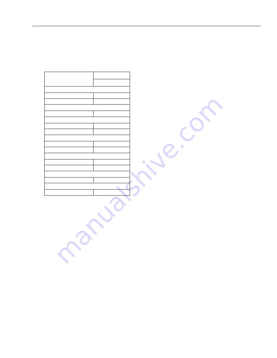
Table 4-1. Function Speeds
Function
Function Speed
In Seconds
Lift
Up
26-32
Down
19-25
Swing Speed
Full 360
70-90
Telescope
Extend
18-23
Retract
23-29
Platform Rotation
Left
9-15
Right
9-15
Jib Boom (460SJ)
Up
17-23
Down
13-20
Drive Speed (2WD)
27-32 @ 200ft.
Drive Speed (4WD)
46-115 @ 50ft.
Summary of Contents for JLG 400S
Page 1: ...Service and Maintenance Manual Models 400S 460SJ P N 3120895 December 6 2012...
Page 2: ......
Page 20: ...xvi JLG Lift 3120895 LIST OF TABLES TABLE NO TITLE PAGE NO This page left blank intentionally...
Page 52: ...SECTION 2 GENERAL 2 14 JLG Lift 3120895 NOTES...
Page 100: ...SECTION 3 CHASSIS TURNTABLE 3 48 JLG Lift 3120895 Figure 3 35 Swing Drive Installation...
Page 101: ...SECTION 3 CHASSIS TURNTABLE 3120895 JLG Lift 3 49 Figure 3 36 Swing Motor...
Page 105: ...SECTION 3 CHASSIS TURNTABLE 3120895 JLG Lift 3 53 Figure 3 38 Swing Brake S N 64802 to Present...
Page 107: ...SECTION 3 CHASSIS TURNTABLE 3120895 JLG Lift 3 55 Figure 3 39 Swing Torque Hub...
Page 124: ...SECTION 3 CHASSIS TURNTABLE 3 72 JLG Lift 3120895 Figure 3 44 EFI Component Location...
Page 136: ...SECTION 3 CHASSIS TURNTABLE 3 84 JLG Lift 3120895 Figure 3 49 Valve Location Chassis...
Page 137: ...SECTION 3 CHASSIS TURNTABLE 3120895 JLG Lift 3 85 Figure 3 50 Hyd Tank Installation...
Page 143: ...SECTION 3 CHASSIS TURNTABLE 3120895 JLG Lift 3 91 This page left blank intentionally...
Page 155: ...SECTION 3 CHASSIS TURNTABLE 3120895 JLG Lift 3 103 Figure 3 60 EMR2 Fault Codes Sheet 1 of 5...
Page 156: ...SECTION 3 CHASSIS TURNTABLE 3 104 JLG Lift 3120895 Figure 3 61 EMR2 Fault Codes Sheet 2 of 5...
Page 157: ...SECTION 3 CHASSIS TURNTABLE 3120895 JLG Lift 3 105 Figure 3 62 EMR2 Fault Codes Sheet 3 of 5...
Page 158: ...SECTION 3 CHASSIS TURNTABLE 3 106 JLG Lift 3120895 Figure 3 63 EMR2 Fault Codes Sheet 4 of 5...
Page 159: ...SECTION 3 CHASSIS TURNTABLE 3120895 JLG Lift 3 107 Figure 3 64 EMR2 Fault Codes Sheet 5 of 5...
Page 208: ...SECTION 3 CHASSIS TURNTABLE 3 156 JLG Lift 3120895...
Page 210: ...SECTION 3 CHASSIS TURNTABLE 3 158 JLG Lift 3120895...
Page 213: ...SECTION 3 CHASSIS TURNTABLE 3120895 JLG Lift 3 161...
Page 223: ...SECTION 3 CHASSIS TURNTABLE 3120895 JLG Lift 3 171 Sensor Transducer Type...
Page 227: ...SECTION 3 CHASSIS TURNTABLE 3120895 JLG Lift 3 175 Sensor Transducer Type...
Page 229: ...SECTION 3 CHASSIS TURNTABLE 3120895 JLG Lift 3 177...
Page 231: ...SECTION 3 CHASSIS TURNTABLE 3120895 JLG Lift 3 179...
Page 233: ...SECTION 3 CHASSIS TURNTABLE 3120895 JLG Lift 3 181...
Page 235: ...SECTION 3 CHASSIS TURNTABLE 3120895 JLG Lift 3 183...
Page 237: ...SECTION 3 CHASSIS TURNTABLE 3120895 JLG Lift 3 185...
Page 255: ...SECTION 3 CHASSIS TURNTABLE 3120895 JLG Lift 3 203...
Page 259: ...SECTION 3 CHASSIS TURNTABLE 3120895 JLG Lift 3 207...
Page 264: ...SECTION 3 CHASSIS TURNTABLE 3 212 JLG Lift 3120895 NOTES...
Page 288: ...SECTION 4 BOOM PLATFORM 4 24 JLG Lift 3120895 Figure 4 12 Rotator Counterbalance Valve...
Page 303: ...SECTION 5 HYDRAULICS 3120895 JLG Lift 5 15 Figure 5 22 Main Valve...
Page 313: ...SECTION 5 HYDRAULICS 3120895 JLG Lift 5 25 Figure 5 25 Variable Displacement Hydraulic Pump...
Page 402: ...SECTION 6 JLG CONTROL SYSTEM S N 61718 TO PRESENT 6 86 JLG Lift 3120895 NOTES...
Page 460: ...SECTION 7 BASIC ELECTRICAL INFORMATION SCHEMATICS 7 58 JLG Lift 3120895 NOTES...
Page 461: ......


