Zone
Zone
TROUBLESHOOTING
VCB-X Controller Field Technical Guide
80
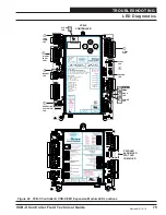
LED Diagnostics
Diagnostic LED Operation
POWER LED Operation
When the VCB-X Controller is
fi
rst powered up, the POWER LED
should light up and stay on continuously. If it does not light up,
check to be sure that you have 24 VAC connected to the controller,
that the wiring connections are tight, and that they are wired for the
correct polarity. The 24 VAC power must be connected so that all
ground wires remain common. If after making all these checks, the
POWER LED does not light up, please contact WattMaster Controls
Technical Support for assistance.
Diagnostic LED Operation
When power is
fi
rst applied, the STATUS 1 and STATUS 2 LEDs
will be off for 1 second. At this time, both LEDs will blink to
indicate the setting of the address switch and then will extinguish
for 5 seconds. Verify that the address switch setting is correct by
counting the number of blinks.
If the address switch is not correct,
fi
rst remove the communication
loop terminal plug from the controller and then from the power
terminal plug. Set the address dip switches correctly. See
Figure
41
for correct address switch setting instructions. After you are
sure the address switch setting is correct,
fi
rst reconnect the power
connection and then reconnect the communication loop connection
to the controller.
NOTE:
You must always cycle power to the Controller being
addressed after changing address switch settings in
order for the changes to take effect.
Reapply power to the controller and observe the blink code to verify
the address is set correctly. If the STATUS 1 and STATUS 2 LEDs
now blink the correct address, your controller is addressed correctly.
If they don’t light up at all, the controller is not operating correctly
and could be defective. Once the controller is done blinking the
address, the LEDs will blink a code every 10 seconds to indicate
controller status. If all of these tests are made and the controller
still doesn’t operate, please contact WattMaster Controls Technical
Support at 866-918-1100.
The Blink Code Descriptions in
Table 6
cover multiple alarm
conditions. You will need to use one of the Orion Interface Tools to
determine the speci
fi
c alarm condition. See the Alarm descriptions
on pages 66 through 68 for further details.
Digital Compressor LED Operation
UNLOAD LED
Any time there is a signal going to the Digital Compressor Unloader
Solenoid Valve the Unload LED will be on.
ALERT LED
The ALERT LED will blink the alarm codes for the digital
compressor. See
Table 7
.
Blink Code Description
STATUS 1
LED
Blinks
STATUS 2
LED
Blinks
NORMAL OPERATION
0
1
SUPPLY AIR SENSOR FAILURE
1
2
OUTDOOR AIR SENSOR FAILURE
2
2
SPACE SENSOR FAILURE
3
2
MISSING EXPANSION MODULE*
4
2
CO2 SENSOR FAILURE
6
2
AIRFLOW SENSOR FAILURE*
7
2
MECHANICAL COOLING
FAILURE
1
3
MECHANICAL HEATING FAILURE
2
3
FAN PROVING FAILURE
3
3
DIRTY FILTER ALARM
4
3
EMERGENCY SHUTDOWN
5
3
ECONOMIZER TITLE 24 ALARM
6
3
LOW SUPPLY TEMP ALARM
1
4
HIGH SUPPLY TEMP ALARM
2
4
CONTROL TEMP HI ALARM
3
4
CONTROL TEMP LOW ALARM
4
4
HIGH HEAD PRESSURE
5
4
WATER PROOF FAILURE
6
4
SUCTION PRESSURE ALARM*
7
4
LOW LEAVING WATER TEMP
8
4
PUSH BUTTON OVERRIDE
1
5
OUTPUT FORCE ACTIVE
0
6
* MISSING EXP. MODULE – INCLUDES MULTIPLE MODULES
AIRFLOW SENSOR FAILURE – INCLUDES MULTIPLE AIRFLOW
SENSORS
SUCTION PRESSURE ALARM – INCLUDES SUCTION PRESSURE
SENSOR FAILURE ALARM, LOW SUCTION PRESSURE ALARM,
AND UNSAFE SUCTION PRESSURE ALARM
Table 6: Diagnostic LED Blink Code Interpretation
Blink Code Description
ALERT
LED
Blinks
NORMAL OPERATION
0
MISSING DISCHARGE SENSOR
1
HIGH TEMPERATURE CUTOFF TIMEOUT
PERIOD (30 MINUTES)
3
HIGH DISCHARGE TEMPERATURE CUTOFF
4
COMPRESSOR LOCKED OUT
6
Table 7: ALERT LED Blink Code Interpretation
Revised 6/17/14

