VCB-X Controller Field Technical Guide
INSTALLATION & WIRING
47
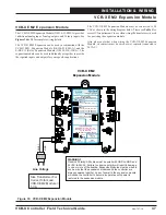
VCB-X EM2 Expansion Module
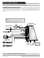
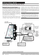
Figure 33: VCB-X EM2 Expansion Module
24V
AC
GND
VCB-X EM2
Expansion Module
WARNING!!
Observe Polarity! All boards must be wired with GND-to-GND and
24VAC-to-24VAC. Failure to observe polarity will result in damage
to one or more of the boards. Expansion Modules must be wired in
such a way that the expansion modules and the controller are
always powered together. Loss of power to the expansion module
will cause the controller to become inoperative until power is
restored to the expansion module.
Line Voltage
Size Transformer For
Correct Total Load.
VCB-X E
Module =
5 VA
M2
GND
GND
+24 VAC
ANALOG INPUT TB
BINARY INPUT TB
ANALOG OUTPUT TB
WattMaster Label
#L102189
Rev.: 1C
B
E-BUS
CONNECT
E-BUS
CONNECT
24 VAC POWER ONLY
WARNING!
POLARITY MUST BE
OBSERVED OR THE CONTROLLER
WILL BE DAMAGED
POWER INPUT TERMINAL BLOCK
AAON: V35130
RETURN AIR BYPASS DAMPER
RETURN AIR DAMPER
ECONO FEEDBACK / RST SIG
REMOTE FORCED COOLING
REMOTE FORCED HEATING
REMOTE FORCED DEHUMID.
GND
GND
www.aaon.com
www.orioncontrols.com
ANALOG OUTPUT TB
OE336-23-EM2
VCB-X EM2 EXPANSION MODULE
VCB-X EM2 Expansion Module
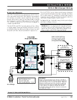
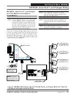
The VCB-X EM2 Expansion Module ( OE336-23-EM2-A) provides
1 additional analog input, 2 analog outputs, and 3 binary inputs. See
Figures 34 & 35
for complete wiring details.
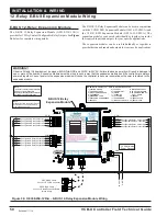
The VCB-X EM2 Expansion can be used in conjunction with the
VCB-X EM1 Expansion Module ( OE336-23-EM1-A) and the
E-BUS 12-Relay Expansion Module (OE358-23E-12R-A). The
expansion modules can be used individually or together to provide
the required inputs and outputs for your speci
fi
c applications.
The VCB-X EM2 Expansion Module must be connected to 24
VAC as shown in the wiring diagram below. Please see
Table 1
for
correct VA requirements to use when sizing the transformer(s) used
for powering the expansion module.
Also please note that when wiring the VCB-X EM2 Expansion
Module, its contacts must be wired as wet contacts (connected to
24 VAC).
New 7/17/14

