Zone
Zone
INSTALLATION & WIRING
VCB-X Controller Field Technical Guide
44
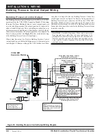
Building Pressure Control Output Wiring
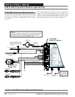
Figure 30: Building Pressure Control Output Wiring Diagram
Building Pressure Control Output
The Building Pressure Control Output is a 0-10 VDC or 2-10 VDC
signal sent from the VCB-X EM1 Expansion Module. When using
the output for Direct Building Pressure Control (output signal rises
on a rise in building pressure), the output signal can be connected to
either a Variable Frequency Drive controlling an exhaust fan or to
a damper actuator controlling an exhaust damper (both by others).
When used in this manner, the output signal must be con
fi
gured for
Direct Acting operation. See
Figure 30
below for detailed wiring
of the Building Pressure Control Output Signal.
When using this output for Reverse Building Pressure Control
(output signal rises on a fall in building pressure), a damper actuator
controlling an OA Damper or Supply Fan VFD would be used. When
using the OA damper for Reverse Building Pressure Control, the
output signal must be con
fi
gured for Reverse Acting operation. A
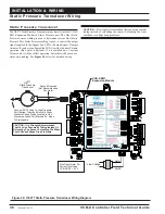
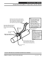
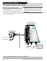
Building Pressure Sensor connected to SIG1 on the VCB-X EM1
Expansion Module is used to sense and control the signal to the
Building Pressure Output. The OE258-01 Building Static Pressure
Sensor must be connected in order for the Building Pressure Output
to operate correctly.
CAUTION:
Variable Frequency Drive units can cause
large transient noise spikes that can cause interference to be
propagated on other electronic equipment. Use shielded wire
wherever possible and route all sensor and controller wiring
away from the Variable Frequency Drive and the HVAC unit
electrical wiring.
VCB-X EM1
Expansion Module
AOUT1
24VAC
GND
Line Voltage
Size Transformer For
Correct Total Load.
VCB-X E 1 Module = 5 VA
M
0-10 VDC Input From AO1
GND
GND
Shield
Shield
24 V
A
C
GND
+
+
Building Pressure Control
Exhaust Fan Variable Frequency Drive
(By Others)
_
GND
Caution: The VFD Unit Must Be
Configured For 0-10VDC Input. The Input
Resistance At The VFD Must Not Be
Less Than 1000 Ohms When Measured
At The VFD Terminals With All Input
Wires Removed.
Building Pressure Control
Damper Actuator
(By Others - Belimo Actuator Shown)
Wiring When Using Damper Actuator
For Building Pressure Control
Both Types Of
Building
Pressure Control
Devices Are
Shown
Only One Type
Of Building
Pressure Control
Device May Be
Used On Each
HVAC Unit
Wiring When Using Exhaust Fan VFD
For Building Pressure Control
3 Y1
2
1 - COM
Belimo Actuator Wiring
Shown. Consult
Factory For Other
Manufacturer Wiring
Instructions
+
Note:
Wire To The VFD Using 18 GA
Minimum 2 Conductor Twisted Pair
With Shield Cable. Wire Shield To
GND As Shown
GND
BUILDING PRESSURE
1
2
Revised 7/30/13


