Zone
Zone
INSTALLATION & WIRING
VCB-X Controller Field Technical Guide
48
VCB-X EM2 Input Wiring
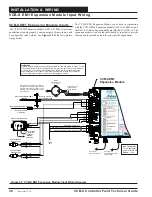
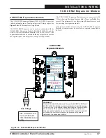
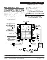
Figure 34: VCB-X EM2 Inputs Wiring
REMOTE FORCED COOL - N.O. CONTACT
REMOTE FORCED DEHUM.- N.O. CONTACT
REMOTE FORCED HEAT - N.O. CONTACT
GND
BIN2
BIN3
+
-
24V
AC
GND
AIN1
BIN1
VCB-X EM2
Expansion Module
WARNING!!
Observe Polarity! All boards must be wired with GND-to-
GND and 24VAC-to-24VAC. Failure to observe polarity will
result in damage to one or more of the boards. Expansion
Modules must be wired in such a way that the expansion
modules and the controller are always powered together.
Loss of power to the expansion module will cause the
controller to become inoperative until power is restored to
the expansion module.
Line Voltage
Size Transformer For
Correct Total Load.
VCB-X E
Module = 5 VA
M2
Title 24 Economizer Feedback
Signal Or Remote Supply Air
Temperature Reset Signal
(Configurable 0-10VDC)
(By Others)
NOTE:
Either The Slide Offset Option For The
Space Temperature Sensor May Be Used
Or The Remote Supply Air Temperature
Reset Signal Option (By Others) May Be
Connected To AIN1 On The VCB-X E 2
Expansion Module. Only One Option Is
Allowed, Not Both.
M
GND
GND
+24 VAC
ANALOG INPUT TB
BINARY INPUT TB
ANALOG OUTPUT TB
WattMaster Label
#L102189
Rev.: 1C
B
E-BUS
CONNECT
E-BUS
CONNECT
24 VAC POWER ONLY
WARNING!
POLARITY MUST BE
OBSERVED OR THE CONTROLLER
WILL BE DAMAGED
POWER INPUT TERMINAL BLOCK
AAON: V35130
RETURN AIR BYPASS DAMPER
RETURN AIR DAMPER
ECONO FEEDBACK / RST SIG
REMOTE FORCED COOLING
REMOTE FORCED HEATING
REMOTE FORCED DEHUMID.
GND
GND
www.aaon.com
www.orioncontrols.com
ANALOG OUTPUT TB
OE336-23-EM2
VCB-X EM2 EXPANSION MODULE
AIN1
Analog Input #1 can be used for one of the following options:
Title 24 Economizer Feedback
If the controller has been con
fi
gured for Title 24 Economizer
operation, the Economizer Actuator Feedback signal will be wired
to this input.
Remote SAT Reset Signal
If Title 24 Economizer operation has not been con
fi
gured, a Remote
Supply Air Temperature Reset Signal can be connected to AIN1 for
applications requiring Remote Reset of the Supply Air Temperature
Setpoint.
When the Slide Offset option on the Room Sensor is used, the Remote
Supply Air Temperature Reset Signal cannot be used. Only one of
these options may be used for VCB-X Controller applications.
This input on the VCB-X EM2 Expansion Module can accept a
con
fi
gurable voltage signal from 0-10 VDC (Direct or Reverse
Acting). See
Figure 34
below for complete wiring details.
BIN1-BIN3 - Remote Forced Cooling,
Heating, and Dehumidifi cation
The VCB-X Controller can be configured to accept 24 VAC
wet contact closures to force the unit into Cooling, Heating, and
Dehumidi
fi
cation. If the Forced Contact con
fi
guration option is
selection, it applies to all three modes. See
Figure 34
below for
wiring details.
New 7/17/14


