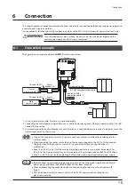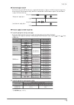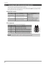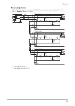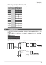
Preparation
11
4-5
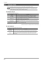
Names and functions of parts
Function setting
switches (SW1)
POWER/ALARM LED
(Green/Red/Blue)
C-DAT/C-ERR LED
(Green/Red)
Cutouts (2 places)
USB communication
connector
Power supply
connector (CN1)
Motor/encoder/
electromagnetic brake
connector (CN2)
RS-485 communication
connector (CN3)
Heat sink
Address number
setting switch (SW2)
Termination resistor
setting switch (SW3)
Type
Name
Description
LED
C-DAT/C-ERR LED (Green/Red)
This LED indicates the status of RS-485 communication.
POWER/ALARM LED
(Green/Red/Blue)
This LED indicates the status of the driver.
Switch
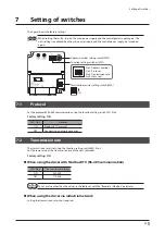
Function setting switch (SW1)
•
No.1: Sets the address number (slave address) of RS-485
communication using together with the address
number setting switch (SW2).
Factory setting: OFF
•
No.2: Sets the RS-485 communication protocol.
Factory setting: ON
•
No.3: Sets the transmission rate of RS-485 communication.
Factory setting: ON
•
No.4: Not used.
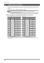
Address number setting switch
(SW2)
Sets the address number (slave address) of RS-485
communication using together with the function setting
switch SW1-No.1.
Factory setting: 1
Termination resistor setting switch
(SW3)
Sets the termination resistor (120 Ω) of RS-485
communication.
Factory setting: OFF
Connector
Power supply connector (CN1)
Connects a main power supply and a control power supply.
Motor/encoder/electromagnetic
brake connector (CN2)
Connects the motor, encoder, and electromagnetic brake.
RS-485 communication connector
(CN3)
Connects the RS-485 communication cable.
USB communication connector
Connects a PC in which the
MEXE02
has been installed.
(USB2.0 mini-B port)


