background image


106 

Symbion™ Programmer Guide 

© Orbotech 2005 


Draft - Confidential


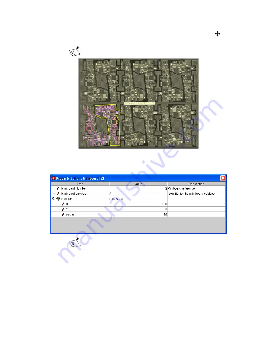
  Rotate the cloned board if necessary by clicking the central marker 

 to 

switch to rotate mode


The rotate tool works in steps of 15°, if free rotation is required 
hold 

Shift

 when using the tool.


  Repeat until all Miniboards are defined.


If the Step and Repeat values are known, the position of each Miniboard can 
be edited in the Property Editor. 


The  Miniboard  number  can  also  be  defined  in  the  Property 
Editor, this number will be used when presenting defect data to 
the repair operator and by Yield Advisor™.


Summary of Contents for Symbion S36

Page 1: ... S3X Author Adam Shaw ads orbotech com Date 05 07 2004 Status Draft Notes Revisions 05 07 2004 First draft begun 19 04 2005 First Draft Version 1 26 04 2005 First Draft Version 2 08 06 2005 First Draft Version 3 15 06 2005 First Draft Version 4 27 06 2005 First Draft Version 5 30 06 2005 First Draft Version 6 Author Approval R D Approval QA Approval Document Approved ...

Page 2: ...Symbion S36 Programmer Guide Draft Internal Use Only Rev 0 Ver 6 ...

Page 3: ...n 08 06 2005 First Draft Ver 3 Changes to chapter order addition of macro block skip information 15 06 2005 First Draft Ver 4 Basic operation section reduced in favor of Operator Guide 27 06 2005 First Draft Ver 5 Section added on OCR Macro Updated 30 06 2005 First Draft Ver 6 Sections updated on saving recipes maintenance solder inspection setup ...

Page 4: ...ew 9 Recipe Graphic 10 Recipe Editor 13 Property Editor 16 Overview 17 View Mode 18 Messages 19 Inspection Recipe Creation 21 Overview 21 Starting the Wizard 22 New Recipe 23 Board Settings 24 Load Board Online Only 25 CAD Import 26 CAD Import Profile Creation 27 Board Geometry 33 Background Image Alignment 35 Fiducial Setup Fiducials in CAD 36 Fiducial Setup Fiducials not in CAD 37 Define Package...

Page 5: ...Mark 61 Setup for Solder Inspection 65 Overview 65 TBA Setup Tool 66 TBA Compatible Inspections 69 Setting up a TBA Inspection 69 Setup for Additional Inspections 71 Overview 71 Condition Inspection 72 OCR 73 Overview 73 Adding OCR 73 Configuration Dialog 74 OCR Parameters 75 Training Characters 77 OCR Training Manager 78 OCR Tips 79 Macro Inspector 81 Overview 81 Adding a Macro 81 Configure a Mac...

Page 6: ...ular Multiboard Definition 105 Multiboard Editing 107 Multiboard Windowize 107 Block Skip 108 Barcode Scanning 111 Overview 111 Recipe Setup 112 Barcode Component Setup 113 Maintenance 115 Overview 115 Test Card 116 Service Maintenance 117 Load the Test Card 118 Camera Alignment Check 120 Brightness Adjustment Check 120 Flash Alignment Check 120 Flash Level Adjustment 121 Grid Adjustment 121 ...

Page 7: ...iv Symbion Programmer Guide Orbotech 2005 Draft Confidential ...

Page 8: ... typographic conventions are used throughout this guide Reference to other documents is shown as Operator Manual Reference within the same document is shown as Typography Menu items are shown as File Menu items to be chosen are shown as File New Buttons and Icons are shown as they appear in the interface User input to be typed is shown as typing Keyboard short cuts are shown as Ctrl C Notes to hel...

Page 9: ...e and Password for the Operating System Have a Username and Password for the Symbion Application The system administrator will provide Username and Password information Be aware of all safety recommendations in the Operator Manual The Symbion is certified inline only The Symbion is intended for operation inline and should not be operated offline with either the Load or Unload aperture open Have re...

Page 10: ... new generation of Automated Optical Inspection AOI Systems The system provides exceptional ease of use with Wizard driven processes following normal Windows application conventions The system incorporates database architecture to facilitate distribution of inspection data and experience throughout an organization ...

Page 11: ...4 Symbion Programmer Guide Orbotech 2005 Draft Confidential ...

Page 12: ...n On the Front Panel press the Green button marked I The computer will begin to boot automatically Once the computer has started you will be prompted to Log In to Windows Use the Username and Password given to you by the Administrator Double click the AOI Server shortcut on the desktop Double click the Symbion S 36 shortcut on the desktop The Welcome screen is displayed when the software has start...

Page 13: ...ministrator The Welcome screen then allows access to those areas of the application your Username and Password permit The larger buttons on the upper part of the wheel provide access to everyday parts of the Application Setup for creation and maintenance of inspection recipes Production for running automatic inspections The smaller buttons on the lower part of the wheel provide access to less freq...

Page 14: ...ted in the display below Click the button labeled No recipe the Recipe Chooser will be displayed Select the Recipe from Chooser and click Open The Inspection button becomes active indicating that inspection can begin If one recipe is used for many variants the Inspection Set must be selected Click the button labeled Default and select the Inspection Set to be used from the list Click the button la...

Page 15: ...u will be prompted if any unsaved changes are found Click the Start button on the Windows Taskbar Click Shut Down Computer Wait a few moments for the computer to shut down removing power before shutdown is complete may result in loss of data The computer will switch off when shutdown is complete Locate the Main Power Switch at the rear of the system turn it to the Off O position ...

Page 16: ...face GUI The Setup Screen reflects the board oriented concept of the system and is made up of the following areas Recipe Graphic 1 Recipe Editor 2 Property Editor 3 Overview View Mode 4 Messages 5 Navigate to the Setup screen by clicking the Setup button on the Welcome screen This is not an exhaustive description of the interface A complete description can be found in Symbion Reference ...

Page 17: ...e is based on the Background Image a picture of the entire product to be inspected Components and their lands are drawn over this image The Recipe Graphic supports Graphic Selection With the tool enabled click a component to select double click a component and all components using the same package will be selected ...

Page 18: ...he dimensions being set The resize tool operates on the following dimensions cycling through in the following order Body Terminal Land Measurement With the tool enabled hold to start measuring and drag over the object to be measured The tool reads out the length measured its individual X and Y components and the angle This tool also provides brightness measurement when not using the measurement fu...

Page 19: ...following layers can be displayed on the recipe Graphic Component Body Draws the component body blue frame when active Terminals Draws the terminals yellow frame when active Lands Draws the package magenta frame and board lands green frame when active Tolerance Draws the location tolerance cyan frame when active Shadows Draws the component shadows gray frame or filled area when active and an angle...

Page 20: ...ame or the Component Name Tag check box to mark unmark a component from a Tag Set A Tagged component may be considered as a remembered selection some special operations are only possible on Tagged components Package the name of the Library Package used for this component The choice of Package determines which inspections are possible as well as the dimensions and characteristics of the component C...

Page 21: ...icient solder Open checks for open solder joints lifted leads Short checks for bridges between terminals or components OCR machine reading of text barcodes Where inspection is possible an inspection is shown either as if enabled or when disabled Double clicking on the checkbox will toggle the state between on and off When an inspection is activated but it not supported by any Inspector the inspect...

Page 22: ... part of the tree this may be the Package name or the name of an Inspection dependant on the location in the Tree Check as in the Table View The following columns are all concerned with the display of inspection results Original when working with images shows the original result stored in the image Verified shows the verified result for the component Current shows the result of the last inspection...

Page 23: ...rity Mark OCR describes the checking of printed text on the device Terminals contains dimension and form information for the component The terminal form defines the expected shape of the solder joint Lands contains the dimensions and offsets of the component lands Inspections describes which inspections should be carried out Some inspections have extra parameters in addition to the activation visi...

Page 24: ...orking in the Graphic Editor with a Zoom View the Overview shows the current zoomed area in a frame Clicking in the Overview panel will cause the Graphic Editor to jump to that area at the current zoom level Dragging in the Overview panel will pan the Graphic Editor at the current zoom level Clicking on the View Mode tab will display that panel ...

Page 25: ... are represented by the Yellow circles Cameras are represented by the white squares The selected light is shown Red the selected camera is shown Blue Clicking a light source will cause the live image to show that light direction Clicking selects the line projector Clicking a camera will cause the live image to show that camera view Clicking on the Overview Mode tab will display that panel ...

Page 26: ...d during recipe verification to list found issues The tabs at the bottom of the Messages panel record the last 10 result sets Selection of a result set will display those results on the Recipe graphic Results are shown with the following icons This component is OK and passed all selected inspections One or more of the inspections was failed ...

Page 27: ...20 Symbion Programmer Guide Orbotech 2005 Draft Confidential ...

Page 28: ... is ready for fine tuning with a small quantity of boards prior to use in Production Inspection The Wizard may be run on either a machine or an Offline Programming Station To create a new Inspection Recipe you will need the following A Symbion S 36 System or Offline Station Component Data for the product Optionally An example of the product after the SMT line An unpopulated board Additional Data M...

Page 29: ... using the Wizard Go to the Setup screen by clicking the Setup button on the Welcome screen Click the New Recipe button in the Tasks list Each step in the Wizard must then be completed before proceeding to the next The steps are described in the following pages As tasks are completed the icon border turns green ...

Page 30: ...dded by the following steps In Recipe Name type in the name to be used Optionally the following may also be provided In Recipe Revision an identifier may be given to differentiate this Inspection Recipe from others with the same name In Product Name a more complete Product Name may be given In Comment any additional information may be typed Once complete proceed to the next step by clicking ...

Page 31: ...ose the Land Finish Type from the drop down list The Land Finish may be Gold Copper or Tin In X Size and Y Size enter the dimensions of the Board The units in which the dimensions are entered can be set in Measuring Unit Click on Set Adapter Width and the rails will be adjusted ready to accept the board Online Only Once complete proceed to the next step by clicking ...

Page 32: ...re a Background Image Click Load Board Take care when loading a board manually into the system Once the board is loaded into the adaptor a Background Image can be acquired Click Acquire Background Image The entire area defined by the Board Size is photographed and presented as a single image in the Graphic Editor Once complete proceed to the next step by clicking ...

Page 33: ...rd Data describing the orientation and relative position of Miniboards Bill of Materials one part number per line with corresponding package information To import data first a Profile must first be selected or a new one created The Profile describes the data format to the system in order to import the CAD Data successfully If you use a consistent format for manufacturing data only one CAD profile ...

Page 34: ...rofile and begin CAD Import Click New Type a name for the Profile in the Field and press Enter Select the Profile and click To re use a Profile Select the Profile and click A Clone of an existing profile re uses all aspects of the profile this is useful for re using package links with a different CAD format ...

Page 35: ...28 Symbion Programmer Guide Orbotech 2005 Draft Confidential Click the check boxes corresponding to each data type available Click ...

Page 36: ... Orbotech 2005 Symbion Programmer Guide 29 Draft Confidential In the Chooser select the correct CAD file and click Open ...

Page 37: ... areas The file to be imported is shown as a preview 1 Filters are available to manipulate the file 2 Delimiter selection 3 Function of columns in the Parsed view 4 The preview and parsed views have tell tales which indicate the state of the translation Errors are shown with red markers and warning with yellow markers clicking a marker will show the problem in the view ...

Page 38: ...on from the list example is shown for Component Data Additional filters are provided for Header Lines ignore a specified number of lines at the top of the file Exclude Include define a rule for identifying lines to be excluded or included The Exclude Include masks use standard wildcards for one or more characters for a single character The Exclude Include masks are case sensitive RefDes Prefix in ...

Page 39: ...tial The CAD Import dialog Once complete proceed to the next step or next data type by clicking If additional files are to be added you can open a file by clicking the Open button in the bottom left corner and selecting the appropriate file from the chooser ...

Page 40: ...und image Within the Geometry dialog the following can be specified Units for the co ordinate data select inch or mm from the drop down list o Scale for the selected unit e g 1 0 0 1 0 01 Units for the orientation data select from degrees or radians o Scale for the selected unit for example 90 when CAD contains orientations 1 2 3 4 Setting the angle scale negatively for example 1 should be used wh...

Page 41: ...ring Flipping Rotation of the entire data is achieved by clicking the orientation marker o Clicking the arrow head of an axis will flip that axis o Clicking the intersection of the axes will exchange them o Clicking in a corner of the board graphic will move the zero to that point When importing Multiboard data the options are repeated for the Multiboard information Once complete proceed to the ne...

Page 42: ...ng Alt and tapping the cursor keys in the direction required Once satisfied with the position click Now a component will be moved and the transform required to make the image fit will be calculated With the Move Tool still selected Select a component close to the opposite corner of the background image Drag the component Hold M1 to the correct location Once satisfied with the position click The sy...

Page 43: ...elect a suitable Fiducial shape from those available in the right of the panel Right click the Fiducial and choose Define Link The Fiducials will be listed in the bottom left of the panel Make two of the Fiducials active by clicking the checkbox in the Active column The Fiducials should be as far apart as possible and ideally diagonally opposite Click to continue to the next step Click Yes to conf...

Page 44: ...clicking at any time Position the Graphic editor so the area to which the Fiducial should be added is clearly visible Select a suitable Fiducial shape from those available in the right of the panel Drag the Fiducial from the Panel to the Graphic Editor Use the Graphic editing tools Move Resize to position and size the Fiducial correctly The Fiducials will be listed in the bottom left of the panel ...

Page 45: ... such as size type and number of terminals The Package also determines how the component will be inspected and for which qualities Select a CAD Package to be defined link is red from the list on the right The components picture from the background image will be shown in the bottom right In case no component is fitted at that location all components of that CAD Package are listed Selecting another ...

Page 46: ...mponent list and select Search CAD Package Type o Click OK Library components with matching names will be displayed Search by JEDEC Parameters o Select the characteristic to filter from the drop down lists on the left for example Material o Select the appropriate value for example Metal More than one filter can be used they are used in combination as a logical AND Library components matching the f...

Page 47: ...lt of the Wizard is checked for errors and missing steps The dialog shows a summary of the results any issues found are listed in the messages panel of the Setup screen Click to Windowize the Recipe and click OK in the following dialog Click to end the Wizard The wizard is now complete before testing can begin any issues found by the Verify Recipe stage should be completed ...

Page 48: ...s checks for the following That all components have been linked Unassigned component shows for each component not linked That the structure of used packages is valid Messages such as Format Terminals will be given according to the particular error That all specified Inspections are possible The Message No Inspector for will be displayed That any configuration options that may affect performance ar...

Page 49: ...components These components must be defined before inspection can be carried out To define a component Select an undefined component You can also select undefined components directly from the Recipe Verification report just click the message in the list Right click and select Define Package from the context menu The Component Definition dialog is displayed ...

Page 50: ...so the first selection should be Discrete Select the most suitable category in each following dialog With each selection the visible Library packages will be reduced You can click any package at any time to see it used in your recipe Enter the number of terminals not for discrete components and click Search click the Next button Set the size in the Recipe Graphic and click Search click the Next bu...

Page 51: ...ion Programmer Guide Orbotech 2005 Draft Confidential At this point you must assign an existing component or create a new one If a good match was found select Yes otherwise select No and click the Next button ...

Page 52: ...as found the system will create a template from the information provided about the size and number of terminals of the package The Industry Name to be used will be pre set as that used in the source CAD file Once the component is properly defined in the Recipe Graphic click Create ...

Page 53: ...otech 2005 Draft Confidential The new package is created in the Library You must select how to update the recipe You can choose between updating by the CAD part number or the CAD Package Once you have made your selection click Finish ...

Page 54: ...s within the recipe Tag Sets and Inspection Sets are accessed through the drop down in the toolbar Inspection Sets are marked with and Tag Sets are marked with To create Tag Sets automatically for each family or Type of components click Edit Inspection Sets The Inspection Set Editor is displayed Inspection Sets are shown on the left with Tag Sets on the right Click the button to create a Tag Set f...

Page 55: ...48 Symbion Programmer Guide Orbotech 2005 Draft Confidential ...

Page 56: ...rd keyboard shortcuts are also employed Cut Ctrl X Copy Ctrl C Paste Ctrl V Delete Delete Component Editing Functions Functions provided for component editing include Insert into a component structure may be used to manually add Pinset Polarity Mark etc It is preferred to use the Property Editor or Component Definition Tool to modify a component Clone the component this command will produce a copy...

Page 57: ...n the current selection Inspections will be reset according to the Inspections defined as default in the Inspection Config Set Package Library Inspections will reset all existing inspections according to the current definition of the package s used in the current selection Set Simple Inspections will reset all existing inspections replacing them with empty tests Set Simple Inspections ONLY if you ...

Page 58: ... components can be stored in a Tagset See Creating Tagsets The following editing options are in the Tag menu Manipulate Tagged Component Common Properties will open a dialog containing all editable properties To edit a property locate it in the tree Changing the Value will change all tagged components A Common Property is one that exists and has the same value in all tagged components ...

Page 59: ... the left A Histogram shows the distribution of the current values Enter the new value correction or factor in the Value field Click on Set to set the value of all tagged components to the specified value Click on to apply the correction to all tagged components Click on x to apply the factor to all tagged components This tool is very useful for manipulating positions of all components simultaneou...

Page 60: ...s panel of the content of the current Tagset This list is interactive selecting any package on the list selects all matching packages A context menu on each package offers the possibility to Tag the components for further editing This tool makes it very easy to work through a recipe fine tuning each package in turn ...

Page 61: ...component with the latest version from the Package Library Update Package in Library will replace the Package in the Library with the version present in the Inspection Recipe When either option is selected you can choose how the update should be applied You can choose to update Selected Component will replace only the selected component with the update from the library Same Package will replace al...

Page 62: ... the exception of lands from the Library Landing Definition will update only the Lands from the Library Warnings will be generated if the selected combination cannot be carried out for example if the Component Definition is updated and the Pin pitch is changed in the Library the Landing Definition cannot be preserved The same mechanism is employed when drag and drop Package updates are made from t...

Page 63: ...ckage used matches the specified text CAD Package searches for components where the Package specified in the CAD source matches the specified text CAD Part No searches for components where the Part information specified in the CAD source matches the specified text Comment searches for components where the Comment matches the specified text Id searches for components with a specific ID A wildcard i...

Page 64: ...n or off and criteria for correct placement are determined by the Location Model Presence reports an error when the component is detected as not fitted Depending on the Inspection Type the Presence error may also be reported together with Billboard and Tombstone Inspection is on or off no other setup is required Billboard reports an error when the component is detected as being placed on its side ...

Page 65: ...on is on or off criteria for inspection are defined by the Polarity Mark tab of the Property Editor Pin Presence reports an error when the end terminals of the component are not detected Inspection is on or off no other setup is required An Inspection which is switched on is indicated by To turn off an Inspection click the checkbox the off state is indicated by ...

Page 66: ...D Use the Box in Box method with a user defined percentage off pad allowance Box in Box 2D Class 1 Use the Box in Box method with an off pad allowance according to IPC Class 1 50 off the land Box in Box 2D Class 2 Use the Box in Box method with an off pad allowance according to IPC Class 2 50 off the land Box in Box 2D Class 3 Use the Box in Box method with an off pad allowance according to IPC Cl...

Page 67: ...hen compared to the found position of the component body Provided the found body position is within the determined bounding box then the Location test will pass Location Model Point In Box The Point in Box Model compares the expected centroid of the component with the found centroid The defined tolerance for example 0 2mm is applied in X and Y about the centroid creating a box The resulting box is...

Page 68: ...olarity of the device Chamfer A sloping edge on the side of the device carrying Pin 1 Corner Chamfer A sloping edge on the corner of the device nearest to Pin 1 Corner Flash A plated mark on the corner of the device nearest to Pin 1 Dark Line A line darker than the background indicating the polarity of the device Dimple A mark in the surface of the device with a rounded profile Flat Hole A mark in...

Page 69: ... the Mark Type is set the system automatically defines a standard size and position for the mark If necessary re size and reposition the polarity mark Select all the component Select the Select Tool from the Toolbar Whilst holding Shift select the mark by clicking inside it A selected sub component is shown in dark red ...

Page 70: ...ol Drag the Handles to resize the Mark so it fits the Polarity Mark on the Device It is necessary that the defined mark covers the Polarity Marking on the device however very accurate definition is not required If all devices of the same package use the same polarity marking the Update Package in Library function will set the same Polarity definition for all components using the package ...

Page 71: ...64 Symbion Programmer Guide Orbotech 2005 Draft Confidential ...

Page 72: ...pections are Solder Volume reports an error when the solder joint is detected as having insufficient or excess solder volume Inspection is on or off the performance of the inspection may be tuned using the TBA Setup Tool Solder Open reports an error when the solder joint is detected as having open solder joints Inspection is on or off the performance of the inspection may be tuned using the TBA Se...

Page 73: ...p of TBA parameters Any change in a parameter is evaluated immediately without re testing The effect of the change is shown graphically The tool can be used for setting up the following types of inspection Solder Volume Solder Shape Lifted Lead Short Detection The tool is accessed through the Recipe Editor Table View by right clicking a suitable inspection and selecting configure from the context ...

Page 74: ...od and bad values An undo button which resets the slider to the start position The slider is reset to the position it was in when the setup tool was opened The effects of moving the slider will be shown interactively in the Inspection Graphic The Graphic shows The image used in this Inspection Method The area s analyzed which are drawn good and bad accordingly Some inspections will show a binarize...

Page 75: ...e the analysis can be expected to be The number of Good Joints with original values and the new settings Original values refers to the result stored with the images the result with the new values is compared to this The number of Bad Joints with original values and the new settings The number of Escapes with original values and the new settings The number of False Alarms with original values and t...

Page 76: ...d in the machine for these steps Acquire an image of the component From the Recipe Table View right click the Inspection to be set up The Recipe Editor views can be switched by clicking in the top right of the Editor From the context menu select configure If no context menu is available this indicates that a suitable Inspector is not available You can check the Inspection Config The TBA Setup Tool...

Page 77: ...70 Symbion Programmer Guide Orbotech 2005 Draft Confidential ...

Page 78: ...quired Tools are provided for more detailed setup of all Solder inspections Possible Other inspections are Condition reports an error when some component specific qualitative defect is detected Inspection is on or off the particular functionality available depends on the Inspection Type OCR reports an error when component legend does not match that specified during setup Inspection is on or off an...

Page 79: ...chip typecheck hk Ensures the correct type is fitted and that a Capacitor is not replaced with a Resistor or vice versa CHIP_CAPACITOR CHIP_RESISTOR chip solderball hk Checks around the component for solder balls These Inspectors are not added as part of Set Default Inspections and have to be set up manually To set up a condition inspection Select the component to be set up In the Property Editor ...

Page 80: ...comprehensive easy to use configuration panel is provided for setup of the OCR Adding OCR To add OCR to a component Select the component on which the macro should be set up In the Property Editor click the OCR tab Double click None in the Type field and select from Black on White White on Black or Laser Etched The system automatically defines the OCR inspection area as approximately 90 of the body...

Page 81: ...l 2 defines the light source s to be used When the dialog opens an automatic light source and camera selection is used to produce the processed image Clicking any light source and camera combination will use that source see View Mode for more information More than one light source may be selected the images are combined by the system Buttons are provided for commonly used lighting combinations OCR...

Page 82: ... Filters can be used to improve contrast in the processed image Brightness Offset will manipulate the processed image When the offset is 0 the image is processed automatically Setting an offset can reduce noise in the image The offset may be both ve and ve Orientation determines the direction relative to the component in which the text should be read Setting default the system reads the text from ...

Page 83: ... for defined pairs of characters Plausible Pairs may be reviewed and defined in the OCR Training Manager Minimum Length defines the minimum expected length of the read text if fewer characters are found the inspection will fail Setting 0 no Minimum Length is required Maximum Length defines the maximum expected length of the read text if more characters are found the inspection will fail Setting 0 ...

Page 84: ...an existing font or type in the name to be used to create a new font Fonts once created may be reused in any recipe It is useful to name the fonts for the device vendor Select the character to be trained Right click and select Train from the context menu In the dialog enter the text to be read for this character For symbols such as multiple characters may be entered such that this is read as c or ...

Page 85: ...the database Review and edit plausible pairs Displays a list of plausible pairs the list can be updated in the dialog by clicking and editing the fields Display information for a specific character Analyze the stored examples with the standard engine Characters correctly recognized by the OCR Engine without training are marked Green Unrecognized characters are marked red characters for which a pla...

Page 86: ... Flat Diagonal lights to achieve the best contrast for standard prints Diffuse is normally best Before manipulating any other parameters or training any characters ensure the best possible contrast by adjusting the Brightness Offset and Lighting Use the Acquire button to check any adjustments to Brightness Offset or Lighting give a stable result Once the best contrast is achieved apply filters and...

Page 87: ...80 Symbion Programmer Guide Orbotech 2005 Draft Confidential ...

Page 88: ...ectors can be added to each component once added to a package the Macros will be stored if the Package Library is updated Adding a Macro To add a macro inspector to a component Select the component on which the macro should be set up In the Property Editor click the Inspectors tab Right Click the Inspectors tab and select Add Inspector Double Click the Undefined Inspector and select one of the mac...

Page 89: ...configure a macro inspector on a component In the Inspectors tab click on the inspector and open it by clicking on Select the Defect to be reported when the test fails Only Inspections supported by the Inspection Type of the component are available Click the Open Config Dialog button ...

Page 90: ...ed Median The brightness value below which half the measured pixels fall StdDev Returns the standard deviation measure of spread of values Pixel Ratio Returns the ratio of pixels between a pair of values specified in Pars Relative Pixel Ratio Returns the ratio of pixels between a pair of values specified in Pars offset by the Mean Trainable Returns the certainty of a match with learned examples se...

Page 91: ...perators are The result is indicated as true or false More complex inspections will require more areas expressions can then be used to evaluate one area in comparison with another 1 2 1 2 10 Clicking in the Expression panel bottom of the right side creates an expression called 1 which can then be defined in the Expression field Use expressions to evaluate the Inspection in smaller parts and to red...

Page 92: ...tial Macro on Terminals When the chosen Defect is terminal oriented Pin Presence Solder Volume Solder Open Short Circuit Any areas defined will be applied to all terminals When working with terminals they are colored for result Green for good and Red for bad ...

Page 93: ... from the context menu Create a new Model by typing a name in the dialog and clicking OK Existing models can be selected from the drop down list Train a good example by selecting Train as good from the context menu Train a bad example by selecting Train as bad from the context menu Create an expression to evaluate the result of the Model Models return a certainty in the range 0 absolutely bad to 1...

Page 94: ...er displays all stored Images in Good and Bad categories Other models may be reviewed by selecting them from the drop down list The following functions are supported Revert the Model to the last saved version Delete the selected Image Train and Save the Model in this state Once the model has been Trained and Saved it is not possible to Revert to an earlier version ...

Page 95: ...n OCV in which the text to be inspected is compared with a stored image To setup an OCV macro Add an OCV area to the Macro Select Configure from the context menu Select the Font ID to be used This will use the same Trained font as OCR Enter the Char to correspond with this image This can be one or more characters space is not allowed ...

Page 96: ...nd click OK An image will be added to the Font ID as this text Create an expression to evaluate the result of the match The result is a measurement of the match between the stored example and that of the inspected component To manage the stored examples Select Activate Train Manager from the context menu The Train Manager is common to the OCR engine see OCR Training Manager for more details ...

Page 97: ...90 Symbion Programmer Guide Orbotech 2005 Draft Confidential ...

Page 98: ...Selected Component drives to the location of the selected component and makes a picture the inspection is then carried out Inspect Current Window inspects all the components contained within the same window as the selected component using the Inspection Manager Inspect Current Selection drives to the location of the selected component and makes a picture using the Inspection Manager Inspect Active...

Page 99: ...corded in the Messages view the Recipe Editor and the Recipe Graphic Errors marked in the Recipe Graphic are shown as circles The results recorded in the Messages view can be re displayed at any time by selecting the appropriate Tab The Editor Messages and Graphic are interactive Selecting a component in one will cause it to be selected in the others ...

Page 100: ...with red boxes around the individual inspections The Recipe Editor views can be switched by clicking in the top right of the Editor In the Tree View it is possible to see which part of the component generated the defects Defects are indicated by the respective icons these can be reviewed in the section Recipe Editor ...

Page 101: ...94 Symbion Programmer Guide Orbotech 2005 Draft Confidential ...

Page 102: ...ave the recipe use any of the following Click on the button bar Choose File Save Ctrl S Choose File Save As F12 From the Recipe Tree choose a folder in which to store the recipe or create one by clicking and entering a name in the dialog The new folder is created under the selected folder In the field Recipe name enter the name to be given to the recipe Click Save The first save may take some time...

Page 103: ...ipes which are released to production To certify a recipe Check the recipe verification is good see Verify Recipe A recipe that still contains errors detected by Recipe Verification cannot be certified Choose File Certify Recipe Ctrl Alt S Confirm the Recipe to be saved is correct and click Save The recipe may continue to be edited but changes will be unavailable to Production until the new versio...

Page 104: ...ards may be defined as either Regular the boards are spaced at regular X Y intervals with the same orientation Irregular boards may have inconsistent spacing or employ different orientations Different procedures are required for creating different types of Multiboard each of these is described below ...

Page 105: ...orrect recipe structure will aid the tracking of production data in the Yield Advisor tool It will also The recipe structure contains 3 key parts when considering Multiboards Frame describes the object inserted into the machine this may be the same as the Board itself or the additional bulk of a carrier Board describes the single manufacturing unit this may be assembled in a Frame and can contain ...

Page 106: ... Frame size is set during the Recipe creation Wizard and shouldn t need to be changed If it is necessary select the Frame in the editor and modify using the Property Editor The Board size should be defined as covering all inspected parts If it is necessary to change the Board size follow the instructions below o Select the Board graphically or in the Recipe Editor o Select the Resize Tool o Drag t...

Page 107: ...ffect on the system performance It does improve the clarity of the display of defect information to the Repair Operator To define the Miniboard shape follow the instructions below o Select the Miniboard graphically or in the Recipe Editor o Select the Resize Tool o Click on the Resize handles to change to Polygon Mode Polygon mode is indicated when the handles are at the corners of the Miniboard f...

Page 108: ...Table View of the Recipe Editor click to switch between the Tree and Table Views o Select all the components in the Board graphically or in the Recipe Editor o Cut the components Edit Cut The components will not be removed until a destination is specified This feature prevents accidental loss of data in the cut and paste buffer o Select the Miniboard and Paste Edit Paste ...

Page 109: ... Fiducials This method is recommended when the Step and Repeat is unknown and has to be found manually Inspection time will be slightly slower with this method To setup a recipe with Global Fiducials This step is most easily achieved in the Table View of the Recipe Editor click to switch between the Tree and Table Views Select the Fiducials graphically or in the Recipe Editor When making a multipl...

Page 110: ...rately defined If the Repeat is not known accurately it can be found during creation of the Multiboard To create a regular Multiboard Select the Miniboard to be repeated Right click and select Array Clone from the context menu The X and Y offset are pre set to the dimensions of the board or miniboard Enter the number of boards to be created in X and Y If the precise offsets are known they should b...

Page 111: ...oolbar Click on the central marker to switch to rotate mode Click on the central marker to switch to Multiboard mode The Multiboard edit marker is shown and handles are added at the top and right of the selection Drag the right handle until the X offset is correct Drag the top handle until the Y offset is correct When satisfied with the values deactivate the Move Tool ...

Page 112: ...iniboards Before defining an irregular Multiboard check The Miniboard size and optionally the shape are correctly defined To define the shape of a Miniboard the Polygon must be edited To create an irregular Multiboard Select the Miniboard to be repeated Right click and choose Clone or press Ctrl D Select the Move Tool from the Toolbar and move the cloned board into position ...

Page 113: ... steps of 15 if free rotation is required hold Shift when using the tool Repeat until all Miniboards are defined If the Step and Repeat values are known the position of each Miniboard can be edited in the Property Editor The Miniboard number can also be defined in the Property Editor this number will be used when presenting defect data to the repair operator and by Yield Advisor ...

Page 114: ...t using the Content Manager Select a component in the Miniboard you wish to edit Switch on the Content Manager in the button bar The icon changes to indicate the tool is active and components will not be drawn for the inactive Miniboards Carry out any editing that is needed The icon changes to indicate that the other Miniboards will be updated when finished When complete click the Content Manager ...

Page 115: ... ensure the work is duplicated on the other Miniboards or Boards see Multiboard Editing for more details Right click and in the context menu select Insert Component A component with an UNDEFINED Inspection Type is added Move and resize the component as necessary In the Property Editor right click the Inspections tab and select Change Inspection Type Tool Setting a Block Skip is also possible with ...

Page 116: ...e Stop on Failure feature The component can also be named in this tab It is also recommended to add the component to the Package Library Windowize the recipe using Tools Windowize Windowize If you used the Content Manager turn it off before Windowize When this component fails testing of the containing Miniboard Board or Frame will be aborted Components with Inspection Type FIDUCIAL or HEIGHT_SYNC ...

Page 117: ...110 Symbion Programmer Guide Orbotech 2005 Draft Confidential ...

Page 118: ...al external scanner connected to the system or optionally by reading the barcode during the inspection cycle Barcode reading during the inspection cycle requires a license and dongle be installed on the system The software Barcode reading is capable of reading the following types Code 39 128 UPC A E EAN 8 13 Interleaved 2 of 5 BC 412 Codabar 2D Data Matrix ...

Page 119: ...er This marker is used to identify how the barcode can be used As read To be added to children for example Miniboards The marker must be added to the Frame To add the Barcode Select the Frame in the Recipe Tree Editor In the Recipe Editor switch between Table and Tree view modes by clicking on Right click and in the context menu select Insert Barcode In the Property Editor choose the Autoincrement...

Page 120: ... more details Right click and in the context menu select Insert Component A component with an UNDEFINED Inspection Type is added Move and resize the component as necessary In the Property Editor right click the Inspections tab and select Change Inspection Type Barcode In the Inspectors tab of the Property Editor check the already added Inspector and if necessary change to barcode linear instant ff...

Page 121: ...114 Symbion Programmer Guide Orbotech 2005 Draft Confidential ...

Page 122: ...n hardware the following calibrations and checks are available Verify the Camera Alignment Verify the Camera Brightness Verify the Flash Alignment Adjust the Flash levels Run the Grid Calibration Run the Adapter Calibration Run the Machine Capability Tests MCT Each of these requires the use of a standard test card which is included with every system ...

Page 123: ...s are verified before release with a standard verified by a certified national laboratory and the density of the grey area is recorded on the back of the card It is recommended to have the grey area verified yearly by an accredited laboratory Care must be taken when handling the Test Card that the grey area remains clean and unmarked Always store the Test Card in the case provided Cross Target The...

Page 124: ...ck The Service Maintenance view is displayed it has two main panels Periodic Maintenance 1 Here the current status of all periodic checks and calibrations is displayed those with red time stamps have expired An expired check or calibration will display a warning on the system The periods over which the checks expire are defined by Orbotech Customer Support Service 2 Most functions here are describ...

Page 125: ...oaded into the adapter by opening the front doors Set X to minimum and Y to maximum to drive the adapter to the front right corner of the system Enter the test card width in the Board Size For CC0103 the width is 178mm for the older TC4797B the width is 220mm Load the Test Card into the Adapter by opening the front doors Slide the Test Card all the way into the adapter as far as the stoppers The O...

Page 126: ...Card to be used Normally the CC0103 is used Click The system tries to align the test card automatically when successful a green check mark is displayed If this fails use the Jog buttons until the cross is in the center of the view and click on Center Cross again The amount of movement caused by the Jog buttons Up Down Left and Right can be adjusted with the Step slider Click ...

Page 127: ...and uses the grey target on the test card Click When the check is completed the date is refreshed and colored for the result A failing check will show a cross in the button If the check fails it may be necessary to adjust one or more cameras refer to Service Manual Flash Alignment Check The Flash Alignment check verifies the proper alignment of the flashes This check is automatic and uses the grey...

Page 128: ... the result A failing check will show a cross in the button If the check fails it may be necessary to replace one or more flash tubes refer to Service Manual Grid Adjustment The Grid Adjustment checks the motion of the machine with respect to the optical head this creates a geometric correction This check is automatic and uses the cross on the test card Click The Adjustment will take approximately...

Reviews: